
Metal detector circuit diagram 5

The metal detector circuit is designed to detect metallic objects by employing an oscillator to generate a frequency signal that varies in response to the presence of metal. The inductor (L) and capacitor (C1) form a resonant circuit that oscillates at a specific frequency. The sensor switch integrated circuit (IC1), specifically the TDA0161D, houses essential components such as the oscillator, detector, and comparator. This integrated circuit plays a crucial role in processing the signals and determining whether a metallic object is present.
Upon detection of metal, the output from IC1 triggers the sound-light alarm circuit, which is built around the CD4001 integrated circuit containing four NOR gates (IC2). The output from the detector is fed into these NOR gates, which can be configured to activate the alarm system. The sound-light alarm circuit includes a high-brightness light-emitting diode (VL) that visually indicates detection and a speaker (BL) that emits audible alerts.
The resistors (R1 to R6) are selected as 1/4W carbon film types, ensuring stability and reliability in the circuit. Capacitors (C1 to C4) are chosen as ceramic capacitors, known for their low losses and excellent frequency characteristics, which are vital for maintaining the performance of the oscillator. The choice of a 5mm high-brightness LED ensures that the visual alarm is easily noticeable, even in bright environments.
The use of an S9013 or C8050 silicon NPN transistor allows for effective switching capabilities within the circuit, facilitating the control of the alarm components based on the input signal from the sensor switch. Overall, the design of the metal detector circuit integrates these components in a cohesive manner to provide a reliable and efficient means of detecting metallic objects and alerting the user through both sound and light signals.The metal detector circuit consists of oscillator and sound-light alarm circuit, and the circuit is shown as the chart. Oscillator circuit consists of inductor L, capacitor C1, sensor switch integrated circuit IC1 (includes oscillator, detector and comparator circuit, etc.
) and the peripheral components. Sound-light alarm circuit consists of four NOR gate integrated circuit IC2 (Dl ~ D4) and the light-emitting diode VL, speaker BL and other components. R1 ~ R6 select 1/4W carbon film resistors. C1 ~ C4 select ceramic capacitors. VL selects 5mm high-brightness light-emitting diode. V uses S9013 or C8050 silicon NPN transistor. IC1 uses TDA0161D sensor switch integrated circuit; IC2 selects CD4001 four NOR gate integrated circuit.
🔗 External reference
Related Circuits
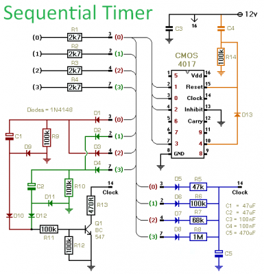
This timer is designed to generate a sequence of up to ten distinct events. Each event's duration can be set independently, and the sequence can be configured to run a predetermined number of times or continuously. Additionally, the individual...
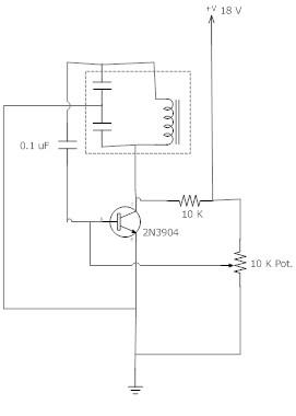
The frequency remains stable as the voltage decreases. It is referred to as the "backwards JT" because it operates optimally with a bifilar coil and a single transistor. With a modification to the circuit, it is possible to deplete...
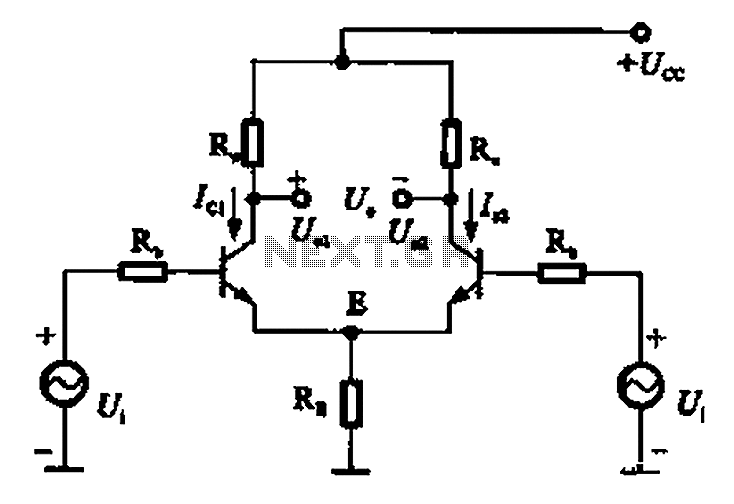
The common mode signal of an emitter-coupled differential amplifier circuit assumes that two equal small increases of the same polarity signal, referred to as the common mode signal, occur simultaneously. This results in an increase in the potential at...
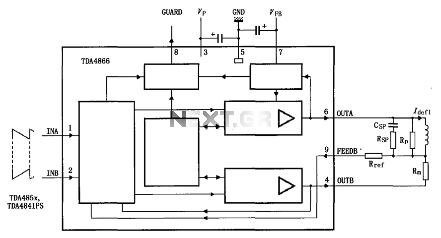
The TDA4866 is a 90-color power amplifier designed for vertical deflection systems, operating at a frequency range of 50 to 160 Hz. The CRMM circuit is implemented to ensure a high current drive input. The amplifier features a dual...
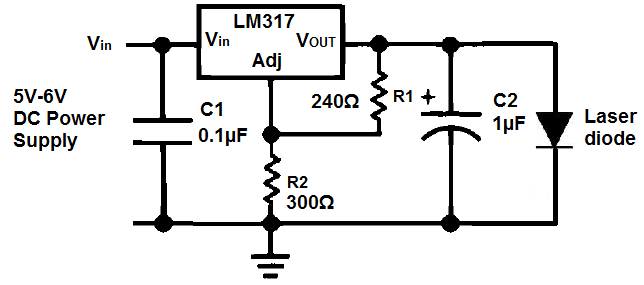
Unlike LED light, a laser's light output is more concentrated, resulting in a smaller and narrower viewing angle. This characteristic necessitates that the laser light be directed more precisely at its source for effective detection. Laser light is also...
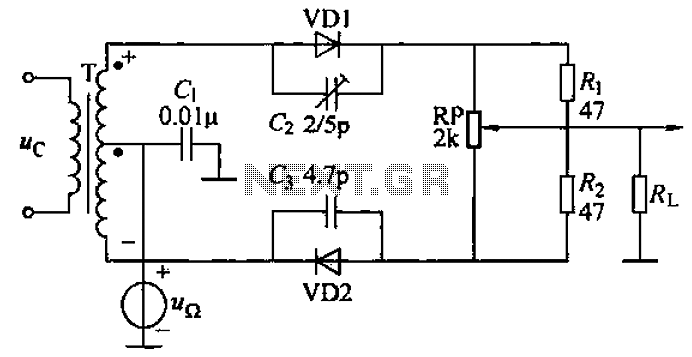
A common diode balanced modulator circuit is illustrated. It comprises two identical performance diodes and a center-tapped transformer configuration. The diodes used are VD1 and VD2, specifically 2AP9 models. The parameters for the circuit elements are detailed in FIG....