
Common mode signal of emitter-coupled differential amplifier circuit a

The emitter-coupled differential amplifier is a key component in analog signal processing, particularly in applications requiring high precision and noise immunity. In this configuration, two identical transistors are used, with their emitters connected together and biased by a common resistor. The differential input allows the circuit to amplify the difference between two input signals while rejecting any signals that are common to both inputs, known as common mode signals.
The operation of the circuit relies on the principle of negative feedback. When a common mode signal is applied, both transistors experience an equal increase in their base-emitter voltages, leading to a simultaneous increase in collector currents. This results in a rise in the voltage at the common emitter point (point U). The negative feedback mechanism works by adjusting the output to counteract any changes caused by the common mode signal, thus stabilizing the output voltage and reducing the overall gain for common mode signals. This is quantified by the common-mode rejection ratio (CMRR), which is a measure of the circuit's ability to reject unwanted common mode signals.
In practical applications, such as audio power amplifiers, the differential amplifier configuration is utilized to improve performance by minimizing zero drift and enhancing the signal-to-noise ratio. By employing two sets of differential amplifiers, the circuit can effectively cancel out noise and interference that may be introduced from various sources, such as power supply fluctuations or electromagnetic interference. This design approach not only enhances the fidelity of the audio signal but also ensures that the amplifier operates reliably across a wide range of conditions, making it suitable for high-quality audio applications. Common mode signal of emitter-coupled differential amplifier circuit a At the input of the circuit is assumed that two equal small increase, of the same polarity signal (referr ed to as common mode signal), as shown in (a), is seven and I will increase at the same time as, where the current flowing through the Ie ICI + ICZ. Thus, e point potential U increases, the current negative feedback to play the role. In other words, common mode input signal existence introduces a strong negative feedback, so that the common-mode magnification greatly reduced and, therefore, reduce the zero- point drift.
Figure (b) shows examples of the differential amplifier applications in audio power amplifier circuit. Use two sets of input differential amplifier circuit in the amplifier. Thereby effectively suppressing the generation of zero drift, reducing the influence of noise and interference.
Related Circuits
This circuit turns off an amplifier or any other device when it remains idle for 15 minutes. It is powered by the amplifier's tape output. The described circuit functions as an automatic power management system, designed to enhance energy efficiency...
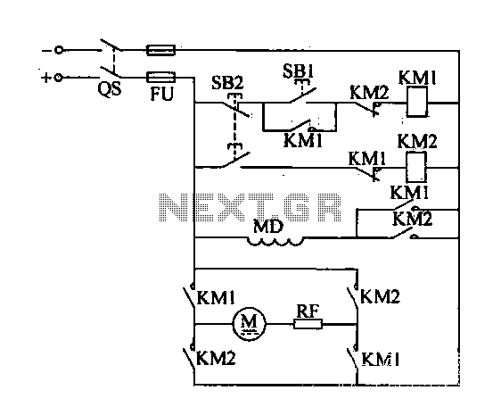
A DC motor reverse brake circuit is presented. To initiate braking, the stop button (SB2) is pressed, which disconnects the move-off contact, causing KM1 to lose power and release. Subsequently, the brake contactor (KM2) is activated. KM2 is designed...
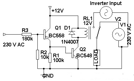
Three weeks ago, an inverter circuit diagram was introduced; however, the circuit did not include the AC to inverter switching part. Today, a 230 Volt AC to inverter switching circuit diagram is being presented. The circuit demonstrates inverter switching....
This schematic illustrates a beeper circuit designed to produce a continuous beep sound while simultaneously flashing an LED. The beeper circuit typically consists of a few key components: a sound-generating device (such as a piezo buzzer), an LED for visual...
Feedback in a public address amplifier should be avoided. The ideal solution is to adjust the positions of the microphone and speaker; however, this is not always feasible in many situations. A frequency shifter that alters the output frequency...
The mixer is the common "virtual earth" mixing amplifier, and there is nothing special about it. Note that it is inverting, which complements the tone controls (also inverting) so the absolute signal polarity is maintained. As shown, the mixer...