
metal detector project circuit

1) The coil L1 is a critical component, with the text stating 15 turns while the schematic indicates 20 turns. Either configuration may function, but the variable capacitor VC1 will differ. It is recommended to start with 15 turns.
2) VC1 is specified as 0-22pF. A minimum of 0pF is unnecessary and challenging to source. With a 15-turn coil, the nominal setting for VC1 is approximately 18pF, suggesting that a 5-15pF capacitor in parallel with a 5 or 10pF fixed capacitor would be more accessible and easier to adjust.
3) The 4-inch coil and 5.5MHz operating frequency will result in a limited detection range, potentially suitable for locating nails within walls behind plaster.
4) The oscillator's V+ should be regulated and isolated from the audio amplifier to prevent interaction with audio signals, as the audio amplifier may draw several hundred milliamps.
5) The power bypass capacitors C1 and C14 may not be effective at the 5.5MHz operating frequency. The detection oscillator may lock onto the frequency of the ceramic filter, necessitating the addition of several 0.1µF (100nF) capacitors to filter the oscillator's V+.
The metal detector circuit schematic presents a combination of components that work together to detect metallic objects. The critical element, the coil L1, serves as the sensor and is essential for the circuit's performance. The discrepancy between the specified 15 turns and the schematic's 20 turns highlights the importance of careful tuning of the coil to achieve optimal sensitivity and detection range.
The variable capacitor VC1 plays a pivotal role in adjusting the resonant frequency of the oscillator circuit. As the nominal setting for VC1 is approximately 18pF with a 15-turn coil, selecting a capacitor configuration that allows for easy adjustments can enhance the circuit's overall functionality. The use of a parallel combination of capacitors can provide a more precise tuning capability, allowing the user to tailor the circuit to specific detection requirements.
The design considerations regarding the 4-inch coil and the 5.5MHz operating frequency indicate that this particular setup may be more suited for detecting small metallic objects at close range, such as nails embedded in walls. This limitation should be taken into account when evaluating the application of this metal detector.
Proper isolation of the oscillator's V+ from the audio amplifier is crucial to prevent interference that could degrade the performance of the audio output. Ensuring that the power supply to the oscillator is stable and free from noise will contribute to clearer audio signals during operation.
Lastly, the inclusion of several bypass capacitors rated at 0.1µF (100nF) is necessary to maintain stable operation at the specified frequency. These capacitors will help filter out high-frequency noise and ensure that the oscillator operates effectively without unwanted interference from other components in the circuit. Overall, careful attention to these design details will enhance the performance and reliability of the metal detector circuit.I have found the schematic diagram on Metal Detector For this class it does not have to be orginal, the project can be taken from the internet. I have a few questions regarding this schematic diagram. There is a small arrow connected from the Emitter of the T3 to the 10n Capacitor C4. What does this arrow mean It appears to me that the arrow is simply indicating signal flow as right to left in that particular wire, which is different from the remaining circuit`s left to right. You would do well to try and locate the "unknown source" that this schematic was "borrowed" from. 1) The most critical component is the coil L1. The text says 15 turns and the schematic says 20 turns. I suppose either will work, but VC1 will be different. I would try 15 turns first. 2) VC1 is 0-22pF. A 0pF minimum is unnecessary, and it would be a difficult to find part. With a 15 turn coil, the nominal setting for VC1 is about 18pF, so a 5-15pF part in parallel with a 5 or 10pF fixed capacitor will be easier to find and easier to adjust.
3) The 4 inch coil and 5. 5MHz operating frequency will give a very limited detection distance. Might be good for finding nails in the wall, behind the plaster. 4) The oscillator V+ should be regulated and isolated from the audio amplifier. Otherwise zero beat will interact with the audio, since the audio amplifier can draw a few hundred mA. 7) The power bypass capacitors C1 and C14 are unlikely to be effective at the 5. 5MHz operating frequency. The detection oscillator will tend to lock on the ceramic filter`s frequency. The circuit needs a few 0. 1uF (100n) caps to filter the oscillator V+. 🔗 External reference
Related Circuits
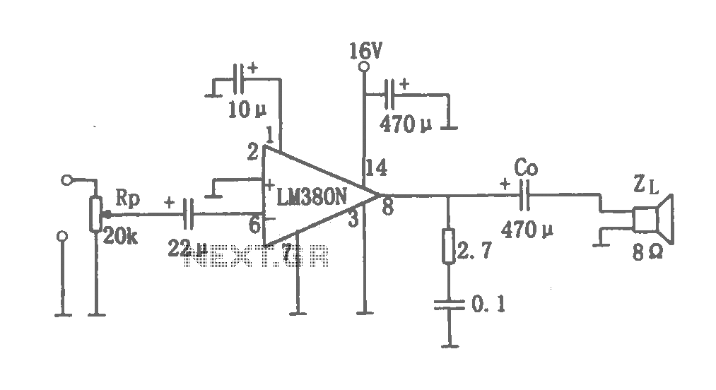
This document details a 2W audio power amplifier circuit that utilizes a 14-pin LM380 package as the amplification element. The input signal is managed by a volume control potentiometer (Rp) rated at 20k ohms, with a coupling capacitance of...
There are two types of solar automatic tracking controllers. One type utilizes a Schmitt trigger light control, which consists of a light sensor and a Schmitt trigger or monostable trigger. The second type employs two light sensors and two...
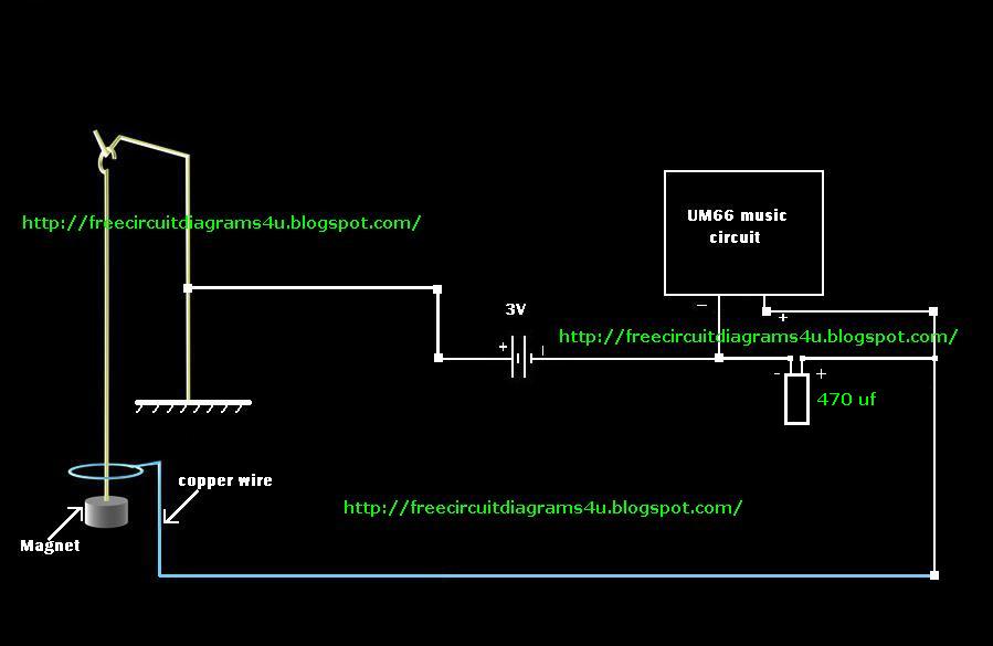
This concept is somewhat different; however, a very simple method has been employed. Many people around the world search for UFOs by observing the sky, and often, wealthy individuals purchase expensive cameras to focus on the sky. In this...
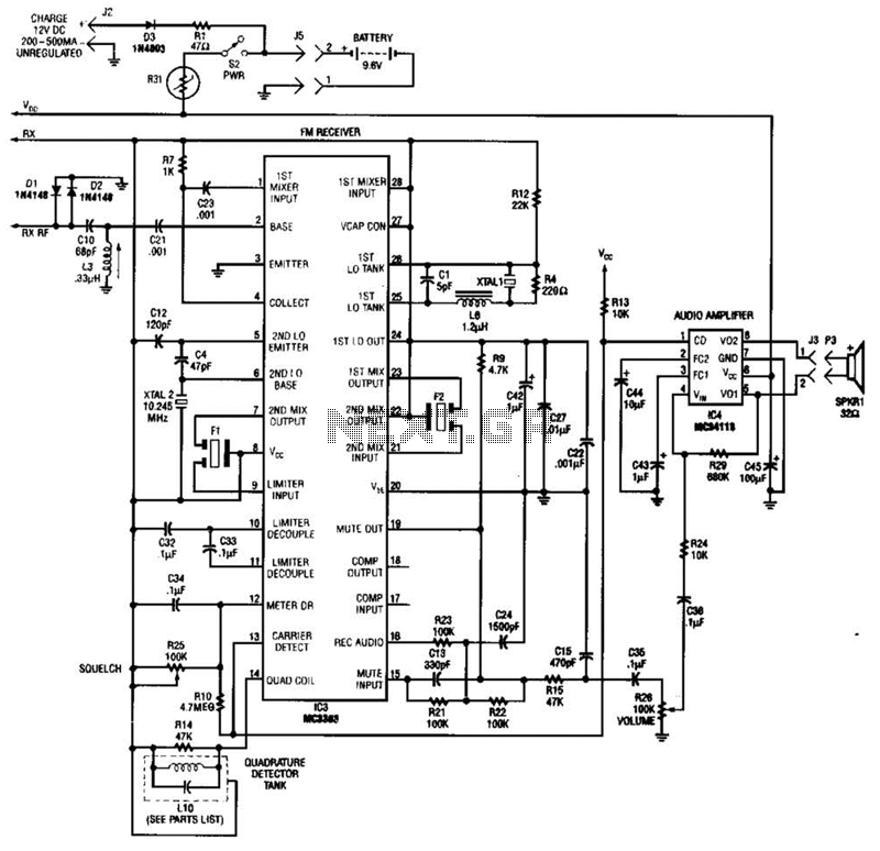
Using a Motorola MC3363 LSI one-chip FM receiver, the circuit is a dual-conversion FM receiver with a 10.7-MHz IF chain. IC4 provides power to drive a small speaker. The described circuit employs the Motorola MC3363 integrated circuit, which is designed...
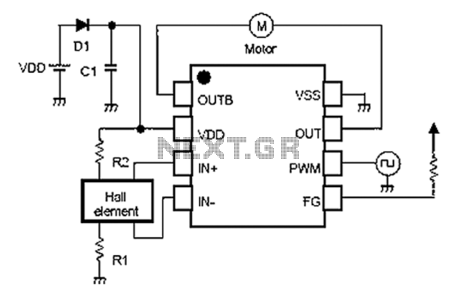
A simple single-phase brushless DC motor drive using the NJU7365 motor driver IC from New Japan Radio Co., Ltd. The NJU7365 is designed for single-phase motor applications and features built-in MOSFET motor drives, direct PWM input, FG output, and...
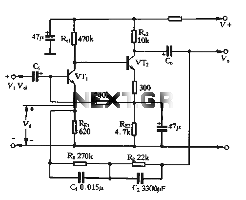
The feedback voltage (Vf) is derived from the output voltage (Vo) through an EQ network. The input voltage (Vf) is related to the subtraction process, yielding a pure input voltage for the circuit, which is associated with the tandem...