
The basic form of frequency equalization circuit

The circuit described involves a feedback mechanism that utilizes the EQ network to stabilize the output voltage by adjusting the input voltage. The feedback voltage (Vf) is critical in controlling the gain of the system, which is represented by the coefficient B. This coefficient is a ratio of the feedback voltage to the output voltage, indicating the effectiveness of the feedback loop in maintaining desired performance characteristics.
The equation B = Vf / Vo illustrates the relationship between the output voltage and the feedback voltage, where REI denotes the resistance in the feedback path, Zm represents a load impedance, and REIo is an additional resistance that contributes to the feedback loop. The total frequency characteristic impedance (ZEQ) of the balanced network plays a significant role in determining the frequency response of the circuit, impacting how the circuit behaves under varying signal conditions.
When the circuit operates without negative feedback, the feedback voltage (Vf) is zero, indicating that the circuit is in an open-loop configuration. In this state, the input voltage (vi) is maintained at a specific level, which allows for an assessment of the circuit's natural gain. The voltage magnification, expressed as V = Vo / Vdi, provides insights into the amplification capabilities of the circuit, highlighting the importance of feedback in achieving stable and predictable performance.
In summary, the circuit's feedback mechanism, characterized by the EQ network and the associated equations, is essential for optimizing voltage control and enhancing the overall functionality of the electronic system. The interplay between the feedback voltage, output voltage, and various resistances defines the operational dynamics of the circuit, ensuring effective performance across different conditions.The figure for the feedback voltage Vf, it is taken from the output voltage Vo by EQ network. Input voltage Vf i and subtraction to give pure input voltage of the circuit belongs Vdjo tandem type negative voltage feedback coefficient B Vf / Vo = REI / Zm + REIo where ZEQ total frequency characteristic impedance balanced network. When the circuit without negative feedback, Vf = OV, V & vi = 'At this point the voltage magnification V- Vo / Vdi.
Related Circuits
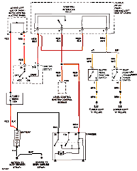
This circuit below shows an electrical circuit applicable for the Audi A4 Quattro 2004 model year. Component: Transmission, Anti-lock Brakes Circuit. The electrical circuit for the Audi A4 Quattro 2004 model year encompasses critical components such as the transmission system...
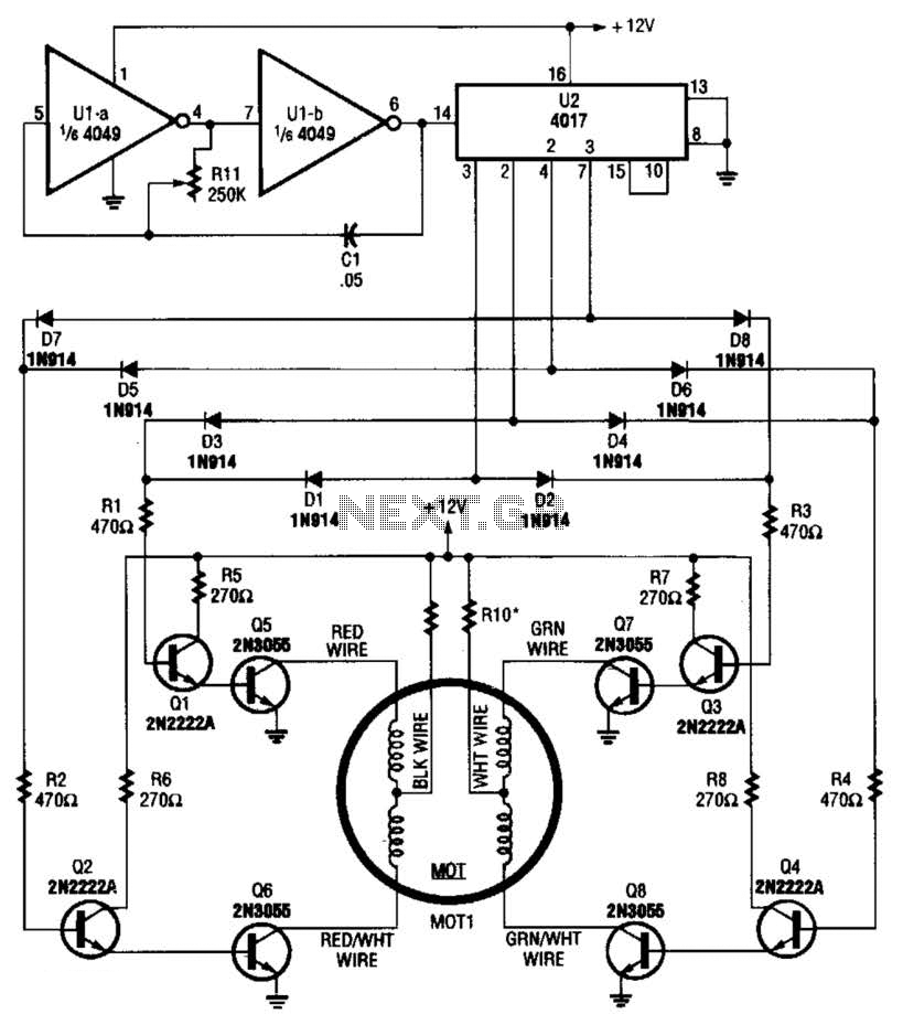
A 4017 decade counter/divider, driven by a low-frequency oscillator (U1-a and U1-b), is employed to control transistor switches that sequence the motor windings as required. The motor (MOT1) is a 12-V stepper motor. Resistors R9 and R10 are chosen...
A clock-and-data recovery (CDR) circuit is utilized to recover the clock from a transmitted data stream and re-time that data with the recovered clock. These circuits are generally positioned at the front-end of receiver chips to extract the clock...
This FM spy transmitter can function as a bug transmitter or a DIY FM bug. It utilizes a single IC 74F13, one coil, a capacitor, and one additional component. The FM spy transmitter is a compact device designed for covert...
This device is a successor to the PIC16C71 4-digit LED frequency counter and voltmeter. It omits some hard-to-find components from the previous version that have been out of production for some time. The earlier PIC16C71 has been replaced with...
The circuit employs two Light Dependent Resistors (LDRs) arranged in series with a separation of approximately half a meter. This configuration allows each LDR to detect the presence of a person entering or exiting the room. The processed outputs...