
Metal Detector using 555 Timer Suite

The metal detector circuit utilizing a 555 timer operates in astable mode, generating a continuous square wave output. This output can be utilized to drive a speaker or alert system when metal is detected. The key components of the circuit include the 555 timer IC, resistors, capacitors, and an inductor coil, which serves as the sensor for detecting metallic objects.
In the astable configuration, the 555 timer produces a pulse-width modulated signal. The frequency of oscillation is determined by the values of the resistors and capacitors connected to the timer. Typically, a low-frequency range is preferred for metal detection, as it allows for better sensitivity to metallic objects. The inductor coil is connected to the output of the timer and is responsible for creating an electromagnetic field. When a metal object enters this field, it disrupts the oscillation, causing a change in the output signal.
The circuit can be further enhanced by incorporating a variable resistor (potentiometer) to adjust the sensitivity of the metal detector. This allows for the detection of different types of metals at varying distances. Additionally, a simple LED indicator can be added to provide a visual cue when metal is detected.
Overall, the simplicity of the 555 timer metal detector circuit makes it an accessible project for electronics enthusiasts and beginners, providing a practical application of basic electronic principles.A actual simple metal detector cyberbanking activity can be advised application a simple 555 timer chip ambit. As you can see in the schematic ambit, this cyberbanking activity requires few alien cyberbanking genitalia.
🔗 External reference
Related Circuits
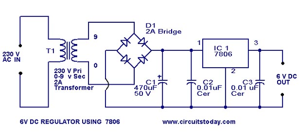
A simple 6-volt DC regulator circuit with a diagram and schematic using the 7806 IC, a positive voltage regulator. It serves as an elementary 6-volt, 1-ampere power supply circuit. The 7806 voltage regulator is a widely used integrated circuit that...
The following circuit illustrates an LM555 integrated circuit (IC) motion detector utilizing infrared sensors. Features include the generation of an infrared pulse modulation at 5 kHz, along with bandwidth control. The LM555 timer IC is a versatile component widely used...

The circuit depicted is designed to protect a system from power supplies that may exceed safe limits. An example of this is small consumer products that utilize external AC adapters, where there is a risk of accidentally connecting the...

A Countdown Timer Circuit is a project submitted by a group of students for their ECE 130 - Computer Application class on August 31, 2006, at the University of St. La Salle, Philippines. The seven-segment decoder is utilized in...
The human eye is highly sensitive to visible light but cannot detect infrared (IR) radiation. This limitation can make it challenging to test or verify equipment that emits infrared radiation. An IR detector circuit has been developed to address...
The IR photo transistor Q1 (Radio Shack 276-145A) or a similar component is connected to the set input (pin 6). It is essential to shield the photo transistor from direct light to ensure that the voltage at the set...