
Precision time-countdown timer

This resistor serves to pull the LOAD COUNTER input low when not in the loading state, which inhibits the BCD output drivers. If the BCD outputs are intended for use, this resistor should be removed, and switch SW4 should be replaced with a Single Pole Double Throw (SPDT) center-off switch.
The circuit's operation is contingent upon the precision of the ICM7213, which provides accurate timing through its crystal oscillator. The 4.1943 MHz crystal is crucial for maintaining the timing accuracy required for the countdown functionality. The ICM7217B counter is designed to count pulses generated by the ICM7213, allowing for precise time measurement and countdown capabilities.
The use of thumbwheel switches enables straightforward user interaction, allowing for easy input of desired countdown times. The ability to preset the register for comparison functions enhances the versatility of the circuit, making it suitable for applications such as digital clocks or timers.
In the context of a 24-hour clock, the register's preset value of 2400 corresponds to the maximum count for hours and minutes in BCD format. The EQUAL output provides a means to reset the counter once the preset time has elapsed, ensuring accurate timing.
Modifications to the circuit, such as removing the 10 kΩ resistor and replacing SW4, can be implemented to enable the use of BCD outputs. This allows for further integration with other digital systems or displays that accept BCD input, expanding the circuit's functionality and application range.The circuit uses an ICM7213 precision one minute/one second timebase generator using a 4.1943 MHz crystal for generating pulses counted by an ICM7217B. The thumbwheel switches allow a starting time to be entered into the counter for a preset-countdown type timer, and allow the register to be set for compare functions.
For instance, to make a 24-hour clock with BCD output the register can be preset with 2400 and the EQUAL output used to reset the counter. Note the 10 k resistor connected between the LOAD COUNTER terminal and ground. This resistor pulls the LOAD COUNTER input low when not loading, thereby inhibiting the BCD output drivers. This resistor should be eliminated and SW4 replaced with an SPDT center-off switch if the BCD outputs are to be used.
Related Circuits
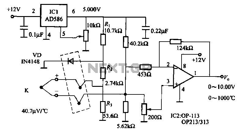
The circuit includes a K-type thermocouple cold junction compensation circuit, a precision 5.000V reference voltage source, and an OP113 operational amplifier. It is capable of measuring temperatures ranging from 0°C to 100°C with a resolution of 0.02°C. The OP113...
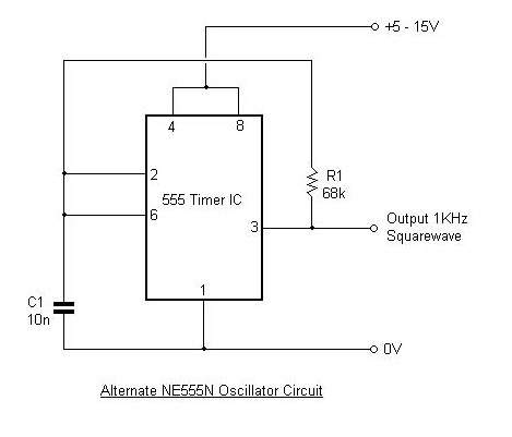
This article outlines the design and applications of the NE555 timer. The content is straightforward and informative, providing valuable insights into various components associated with the NE555. Readers can find and purchase these components through the article. It discusses...
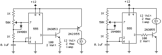
The schematic diagram illustrates a 12 Volt Car Lamp Dimmer Circuit Design utilizing a 555 Timer. This circuit can be employed to dim a standard 25-watt lamp. The 12 Volt Car Lamp Dimmer Circuit utilizes a 555 Timer in astable...
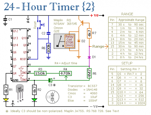
A pair of multi-range timers that provide timing periods of up to 24 hours and beyond. Both timers are fundamentally similar, with the primary distinction being that Version 1 energizes the relay when the time expires, while Version 2...

This 555 timer circuit temperature monitoring system project can monitor temperature at up to four points. The system allows for the selection of whether the alarm should be triggered when the temperature increases or decreases, depending on the resistance...
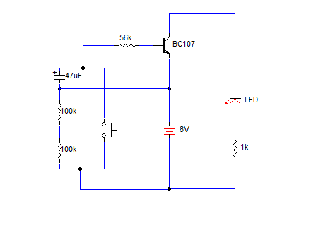
A simple transistorized one-minute delay timer circuit. It does not include any complex or critical components. This circuit can generate a time delay of approximately one minute. When the switch (preferably a push-button type) is pressed, the LED turns...