
Temperature Sensor MAX6698 7-Channel Smart consisting of circuit diagram
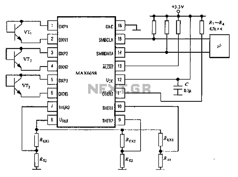
The MAX6698 is a maximum temperature sensor designed for precision thermal monitoring. The circuit operates by utilizing three thermistors, which are resistive temperature devices that change resistance based on temperature variations. Each thermistor (RT1, RT2, RT3) is connected to a corresponding transistor (VT1, VT2, VT3) that acts as a switch to control the output based on the temperature readings.
The internal reference voltage is critical for maintaining the accuracy of the temperature sensing. The resistors (REX1, REX2, REX3) connected to the thermistors ensure that the thermistors are powered correctly, allowing them to provide reliable temperature measurements. The voltage drop across each thermistor is monitored and supplied to the THER pins, which are inputs to the MAX6698, enabling it to determine the maximum temperature among the three sensors.
The choice of transistor models (CMPT3904, SST3904, KST3904-TF, SMBT3904, and FMMT3904CT-ND) is essential for ensuring that the circuit can handle the required switching characteristics and power levels. These transistors are known for their low saturation voltage and fast switching capabilities, making them suitable for temperature sensing applications.
In summary, this circuit configuration effectively utilizes the MAX6698 in conjunction with thermistors and transistors to achieve accurate temperature monitoring and control, suitable for various applications where thermal management is critical. Proper selection of components and careful attention to the circuit design will enhance the performance and reliability of the temperature sensing system. Circuit shown in Figure: MAX6698 maximum temperature with three transistors (VT1 ~ VT3) and three thermistors (RT1 ~ RT3). The internal reference voltage source via a resistor UREF REX1 ~ REX3 were given three thermistor power supply, the voltage drop across the thermistor respectively supplied THER1 ~ THER3 pins. Temperature transistor can be used CMPT3904, SST3904, KST3904-TF, SMBT3904, FMMT3904CT-ND models.
Related Circuits
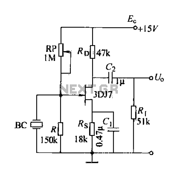
A field effect transistor (FET) voice amplifier has a low input impedance, approximately 1 kΩ, requiring the signal source to provide a constant current signal for operation. Unlike bipolar transistors, FETs are voltage-controlled devices that draw minimal current at...
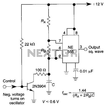
This gated 1-kHz oscillator provides a press-to-turn-on functionality, with waveforms available at the output of pin 3 and across capacitor CI. The gated 1-kHz oscillator circuit is designed to produce a square wave output that can be activated by a...
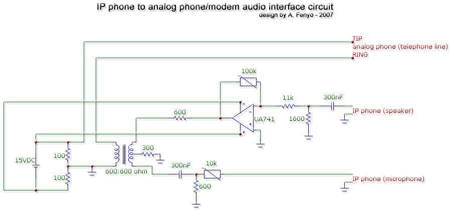
The transformer is a 600:600 ohm transformer, also referred to as a 1:1 ratio 600 ohm transformer. It has approximately the same number of turns on both the primary and secondary coils and is optimized for operation at a...
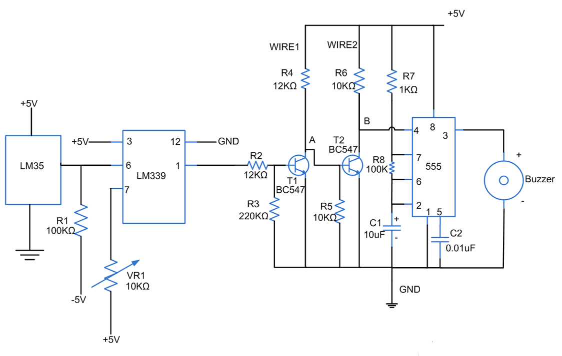
Fires can occur for several reasons, such as forgetting to turn off equipment like irons. A fire alarm circuit with a temperature sensor may be one option to secure homes from fire hazards. There are also fire alarm circuits...
This DC voltage doubler circuit generates a voltage that is double the input supply voltage. It is beneficial when a higher voltage is required from a single lower voltage power source, particularly in applications with low current consumption. The DC...
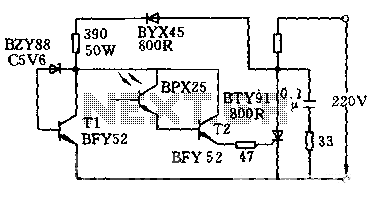
The circuit is designed to activate when the light intensity exceeds 700lx. In this configuration, a phototransistor and the BFY52 transistor are used to trigger the BTY91 thyristor with a current. When light strikes the phototransistor, a positive trigger...