
Gated 1Khz Oscillator (Normally Off) Circuit
")
The gated 1-kHz oscillator circuit is designed to produce a square wave output that can be activated by a momentary press of a switch. The oscillator operates at a frequency of 1 kHz, which is suitable for various timing and control applications. The circuit typically includes a timing resistor and capacitor that determine the frequency of oscillation, while the gating mechanism allows for the output to be enabled or disabled based on an external control signal.
Pin 3 serves as the primary output of the oscillator, delivering the square wave signal. This output can be utilized to drive other components or circuits, such as LEDs, relays, or microcontrollers. The capacitor CI, which is connected across the output, plays a critical role in shaping the waveform and filtering any noise present in the signal. The capacitor may also aid in stabilizing the output by providing a low-pass filtering effect, ensuring that the output waveform is clean and well-defined.
The press-to-turn-on feature enhances user interaction, allowing for easy activation of the oscillator without the need for a continuous switch press. This can be particularly useful in applications where a temporary signal is required, such as in timers or pulse generators. The design can be tailored to include additional features, such as adjustable frequency or amplitude, by modifying the component values or adding further circuitry.
Overall, this gated 1-kHz oscillator is a versatile component that can be integrated into various electronic designs, providing reliable timing signals with straightforward activation. This gated 1-kHz oscillator offers press-to-turn-on operation, A, and waveforms at the output of pin 3 and across CI, B.
Related Circuits
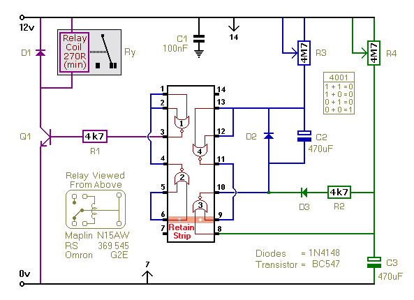
This timer utilizes a basic monostable circuit. The duration for which the relay remains energized, referred to as the ON period, is regulated by the resistor R3 and capacitor C2. Conversely, the duration for which the relay remains de-energized,...
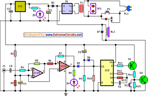
This circuit deactivates an amplifier or any connected device when a low-level audio signal is absent at its input for at least 15 minutes. Activating switch P1 powers the device, enabling operation of any appliance connected to SK1. The...
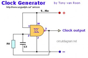
The following diagram represents a Clock Generator circuit that is constructed using NAND Gate logic integrated circuits (ICs). The circuit can utilize either IC 7400 or IC 4011. The 7400 is a TTL (Transistor-Transistor Logic) type, whereas the 4011...
A highly beneficial project involving a crystal tester circuit, also known as an xtal tester circuit, constructed with only a few components. The circuit forms an oscillator that will only oscillate if the crystal under test is functioning properly....
Figure A, B, and C illustrate the test rod end clip, with a positive power supply terminating test equipment. The B and C ends are connected in series with the load, where C represents the negative side of the...
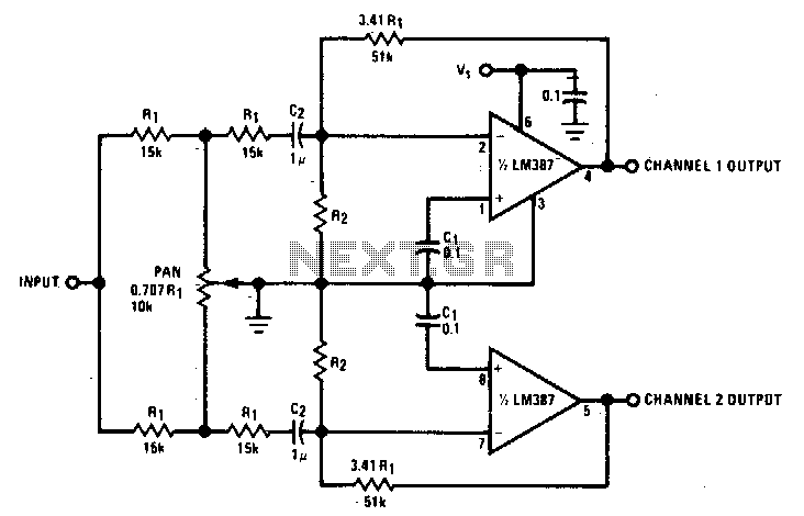
This panning circuit, also known as a panoramic control circuit, allows for the adjustment of the perceived position of a microphone's input across two output channels. This effect is frequently utilized in mixing consoles within recording studios. Panning enables...