
metronome circuit

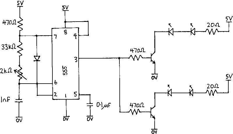
The metronome circuit typically consists of several key components that work together to generate a stable rhythm. At the core of the metronome is an astable multivibrator, often implemented using a 555 timer IC. This configuration allows the circuit to oscillate between high and low states, producing a square wave output. The frequency of this square wave can be adjusted using two resistors and a capacitor, providing musicians with the ability to set the tempo of the beats.
In the schematic, the output of the 555 timer is connected to a transistor, which acts as a switch to drive a small speaker or piezo buzzer. This transistor amplifies the current from the timer output, allowing the speaker to produce audible sound. A resistor may also be included in series with the speaker to limit the current and protect the components from damage.
Power for the circuit can be supplied from a standard battery or DC power supply, with appropriate voltage regulation if necessary. Additional features may include a variable resistor (potentiometer) for fine-tuning the tempo, and LED indicators to visually represent the beat.
Overall, this metronome circuit provides a straightforward and effective solution for musicians seeking to maintain their timing during practice and performance.The figure shows an easy project / schematic of a metronome. A metronome is a device that is used by musicians. The circuit produces continues beats in the speaker.. 🔗 External reference
Related Circuits
The design objective was to produce an hFE tester with switched collector currents for the DUT (Device Under Test) covering a range suitable for the selection and matching of output transistors for amplifiers such as the JLH Class-A, ESP...
The infrared receiver requires the infrared light to be modulated at 38 kHz, which corresponds to a period of 26 µs. The specifications for the receiver suggested using a 50% duty cycle; however, this configuration did not perform as...
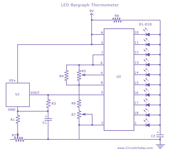
An LED thermometer that can function as a temperature sensor or temperature measurement circuit, utilizing the LM34 for Fahrenheit display or the LM35 for degree Celsius display. The LED thermometer circuit is designed to provide accurate temperature readings using either...
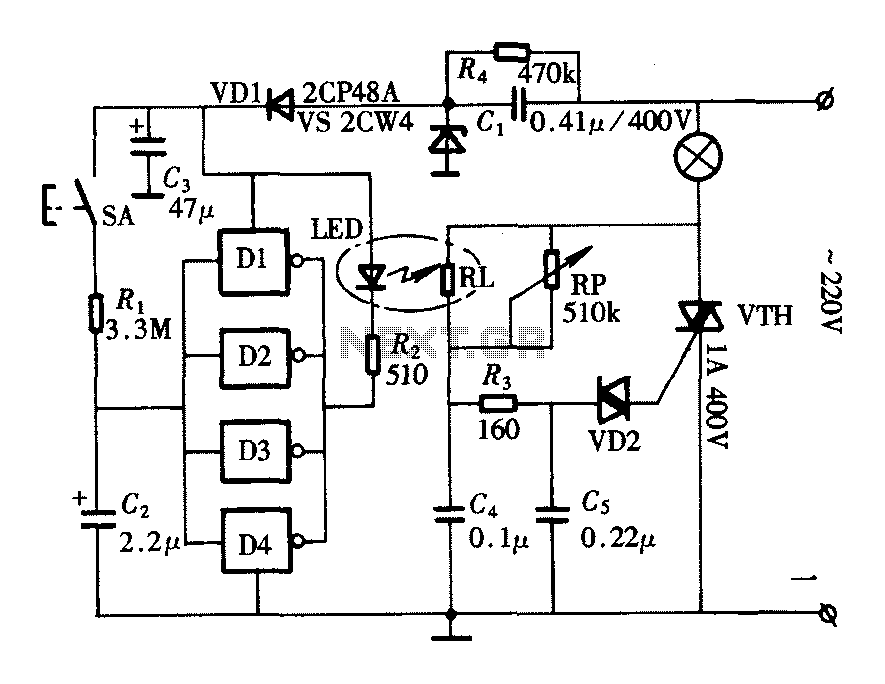
The lighting controller depicted in the figure features a gradual dimming function that prevents sudden brightness changes, which can irritate the human eye and potentially cause damage due to inrush currents. The circuit design includes a six-stage CD4069 inverter...
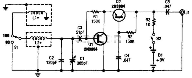
This antenna may assist in minimizing power-line noise. It consists of a plastic hula hoop or conduit with a diameter of 3 feet, which is covered with aluminum foil to serve as a shield for LI and L2. LI...
This USB circuit utilizes an integrated circuit (IC) to convert digital voice data into an analog signal, enabling it to be used with headphones. The output can also be amplified through a power amplifier to drive speakers. The IC...