
microcontroller 8051 rftx rx

The described system involves an RF communication setup utilizing an 8051 microcontroller, the HT640 encoder, and the HT648L decoder. The HT640 encoder converts parallel data from the microcontroller into a serial format suitable for RF transmission. The 8051 microcontroller features a Universal Asynchronous Receiver-Transmitter (UART) that facilitates serial communication, which is essential for interfacing with the RF modules.
In this configuration, the 8051 microcontroller sends 8-bit data to the HT640 encoder. The encoder transforms this parallel data into a serial format, which is then transmitted via RF. The HT648L decoder receives this RF signal and converts it back into a parallel format for the microcontroller or any connected device. It is important to ensure that the baud rate of the UART is compatible with the RF module’s specifications. The maximum data rate of the RF module is 4000 bps, and for reliable communication, the UART should be configured to a lower rate, such as 1200 bps, to ensure that the data is transmitted and received without errors.
Additionally, proper interfacing between the components is critical. The HT640 encoder and the 8051 microcontroller must be connected with appropriate signal lines, ensuring that the data lines are correctly configured. Similarly, the output from the HT648L decoder must be connected to the RX pin of the 8051, allowing the received data to be processed correctly. Any discrepancies in the connections or configurations could lead to the issues described, where the data is not received correctly when the 8051 is connected. Therefore, a thorough check of the wiring, signal integrity, and configuration settings is recommended to resolve the communication issues in this RF system.The problem is when i connect the 8051 to the encoder the data send is not received at the receiver but as soon as the 8051 connections are removed the transmisison works perfectly. thus manually the RF communication works perfectly i. e the 8 bit data which i give manually at the encoder is perfectly send and then later received at the decoder sid
e Is some sort of interfacing required b/w encoder-ht640 and microcontroller 8051 or at the receiver side b/w the decoder-ht648l and 8051. help me plz its urgent these RF modules need data in serial form and the encoder IC is more like a shift register here.
8051`s uart sends data serially. RF modules accepts max datarate of 4000bps normally. so if you keep uart at 1200 bps then uart o/p can be directly connected to transmitter pin. similarly on the other side. receiver`s o/p can be connected to rx pin of 8051. 🔗 External reference
Related Circuits

Utilize a PIC Microcontroller to Control a Hobby Servo. This guide outlines the process of incorporating hobby servos, typically found in remote-controlled airplanes, cars, and similar devices. To implement the control of a hobby servo using a PIC microcontroller, the...

This project demonstrates the use of the 8051 microcontroller to generate PWM outputs for two separate channels. The PWM signals can control the phase angle of SCRs or TRIACs for power regulation of AC loads such as heaters, motors,...
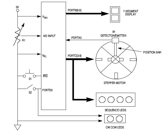
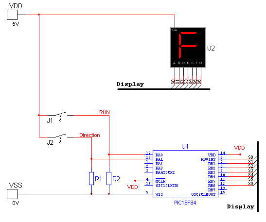
This article explains how to design a stepper motor system using an 8-bit Freescale microcontroller - MC68HC11E9. The design of a stepper motor system utilizing the 8-bit Freescale microcontroller MC68HC11E9 involves several key components and considerations to ensure effective control...
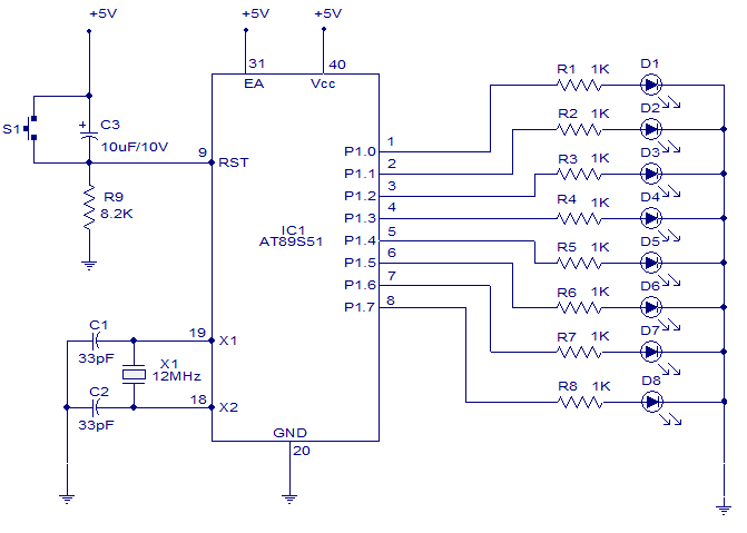
A six-function, eight-channel light chaser utilizing the 8051 microcontroller. The AT89S51, a member of the 8051 family, is employed to produce six distinct lighting sequences. The design incorporates straightforward software and hardware components. The circuit design features the AT89S51 microcontroller...
National Instruments Multisim now features microcontroller unit co-simulation capabilities, enabling the inclusion of a microcontroller, programmed in assembly or C code, within SPICE-modeled circuits. The MCU functionality in Multisim allows students, educators, and professional users to program MCUs in...
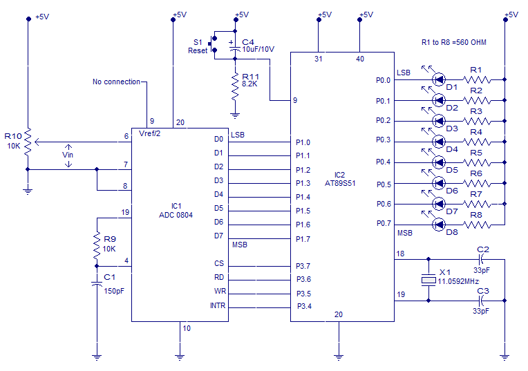
The ADC (Analog to Digital Converter) is a crucial component in numerous embedded projects. This article focuses on interfacing an ADC with the 8051 embedded controller. The ADC0804 model is utilized, and before detailing the interfacing procedure, it is...