
Microcontroller and Motor Driver Circuit Board

The circuit design features a compact integration of a microcontroller and an L298N dual motor driver, which allows for efficient control of two DC motors. The L298N is designed to handle the voltage and current requirements of various motors, making it suitable for robotics and automation applications. Its H-Bridge configuration enables bidirectional control of the motors, allowing for forward and reverse operation.
The layout of the board should be carefully considered to optimize space and minimize the number of wire jumpers. While the programming header is essential for firmware updates and debugging, its inclusion can complicate the layout. It is recommended to position the header in a manner that reduces the need for excessive wiring.
Due to the unique pin spacing of the Multiwatt15 package, custom PCB design may be necessary to accommodate this component. Utilizing a PCB design software allows for precise placement of components and traces, ensuring that the board meets the required specifications. For those who prefer a simpler approach, breakout boards compatible with the L298N can be utilized, which can significantly reduce the complexity of the circuit assembly.
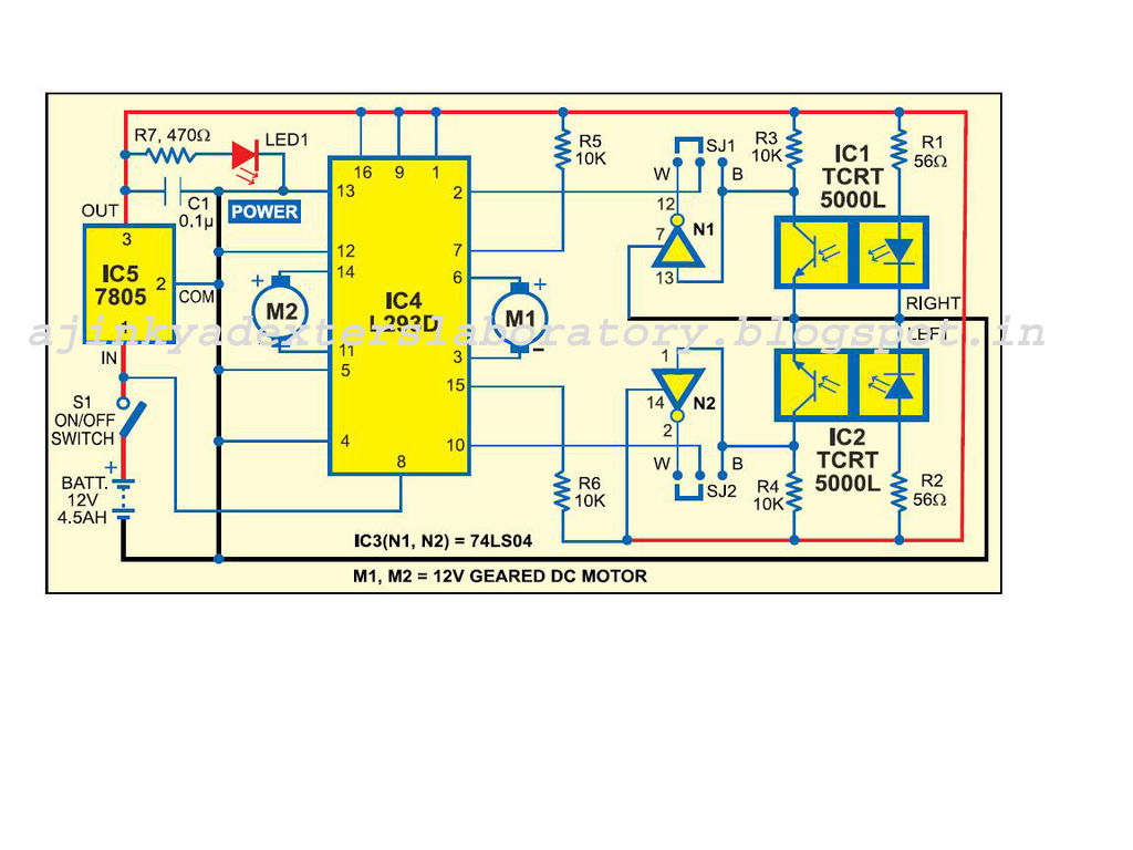
Before finalizing the PCB design for etching, it is crucial to ensure that all unnecessary layers are removed, leaving only the copper traces and drill holes visible. This step is vital for achieving a clean etching process, which will result in a more reliable and effective circuit board. Proper preparation and attention to detail in the design phase will contribute to the overall performance and functionality of the integrated microcontroller and motor driver circuit.Tried to limit the number of wire jumpers in this board but things got a little tight since I was combining the microcontroller and motor driver in one board. It would have been a lot cleaner if I would have left the programming header off. The L298N is a dual motor driver that is essentially a dual H-Bridge motor driver in a compact package.
Since the Multiwatt15 through-hole package doesn`t conform to the 0. 1 ³ spacing of most components, it won`t fit directly into standard perf boards. There are inexpensive breakout boards available if you don`t want to worry about etching. This is the view of the board with all of the components. Before printing for etching, you will want to remove the layers except for traces and drill holes. 🔗 External reference
Related Circuits
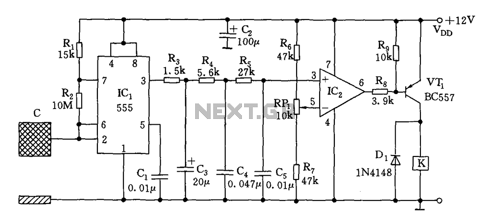
The switch circuit consists of a capacitive oscillator, an integration network, and a comparator circuit that controls a relay. When a body comes close to the induction plate, the inductive capacitance to ground increases, causing the 555 astable multivibrator...
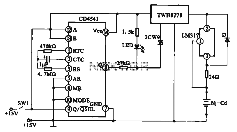
A constant current charging circuit with a long delay is implemented using the CD4541, which constitutes a constant current charging circuit suitable for Ni-Cd batteries. Upon powering on, the CD4541 output at pin high activates the TWH8778 electronic switch,...
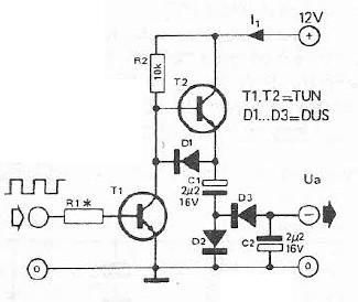
Voltage inverter circuit design electronic project using few electronic components The voltage inverter circuit is a fundamental electronic project that converts direct current (DC) to alternating current (AC). This circuit is particularly useful in applications where AC voltage is required...
Carefully examine the following circuit diagram and attempt to construct the circuit on a breadboard first. If it functions correctly, proceed to create its PCB version. The circuit diagram serves as a blueprint for constructing an electronic circuit on a...
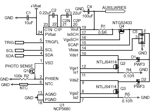
This white LED driver circuit project utilizes the NCP5680 high-efficiency white LED driver integrated circuit (IC). The NCP5680 supports dual power flash LED and torch operations. Its built-in DC/DC converter employs a highly efficient charge pump structure with operating...
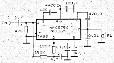
An amplifier circuit is particularly well-suited for use in confined spaces, such as within vehicles. It requires a voltage supply ranging from 9 Volts to a maximum of 17 Volts. This amplifier circuit utilizes the IC MPC575C, which is...