
Voltage inverter circuit design electronic project

The voltage inverter circuit is a fundamental electronic project that converts direct current (DC) to alternating current (AC). This circuit is particularly useful in applications where AC voltage is required but only a DC source is available. The design typically incorporates a minimal number of electronic components, making it both cost-effective and straightforward to implement.
The core of the voltage inverter circuit often consists of a switching mechanism, which can be achieved using transistors or integrated circuits (ICs). These components are responsible for converting the DC input into an AC output by rapidly switching the polarity of the voltage. The most common configurations include the use of a push-pull arrangement or a half-bridge inverter topology.
In a basic design, the circuit may include the following components:
1. **DC Power Source**: This can be a battery or any DC supply that provides the necessary voltage for the inverter.
2. **Switching Devices**: Transistors (such as MOSFETs or BJTs) are commonly used to switch the current on and off, creating the alternating waveform.
3. **Oscillator Circuit**: An oscillator generates a square wave signal that drives the switching devices. This can be implemented using a 555 timer IC or a simple transistor-based oscillator.
4. **Transformer**: A step-up transformer is often included to increase the voltage level of the output AC signal. The transformer also provides electrical isolation between the input and output.
5. **Filter Capacitors**: To smooth out the output waveform and reduce ripple, filter capacitors may be added at the output stage.
The design can be further enhanced by incorporating feedback mechanisms to improve efficiency and stability. For instance, using a microcontroller to manage the switching frequency can optimize performance under varying load conditions.
Overall, a voltage inverter circuit design is an excellent project for understanding the principles of power electronics and the conversion of electrical energy forms. It provides practical insights into circuit design, component selection, and the operation of switching devices in real-world applications.Voltage inverter circuit design electronic project using few electronic components 🔗 External reference
Related Circuits
Most operational amplifier circuits require a dual-polarity power supply - one having +V and -V. However, there are times when a DP supply simply isn't conveniently available. Single-polarity modifications to DP designs often achieve their effect by referencing the...
The digital lock shown below uses 4 common logic ICs to allow controlling a relay by entering a 4 digit number on a keypad. The first 4 outputs from the CD4017 decade counter (pins 3,2,4,7) are gated together with...
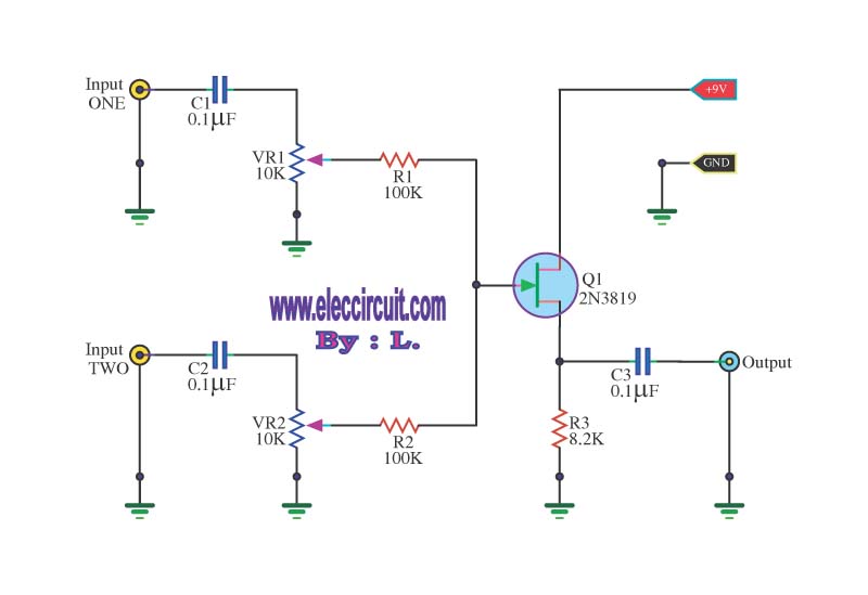
This circuit is a simple mixer circuit that can mix two signal channels into one output channel. It utilizes a codec circuit to convert stereo audio into mono audio. The circuit can also increase the number of channels by...
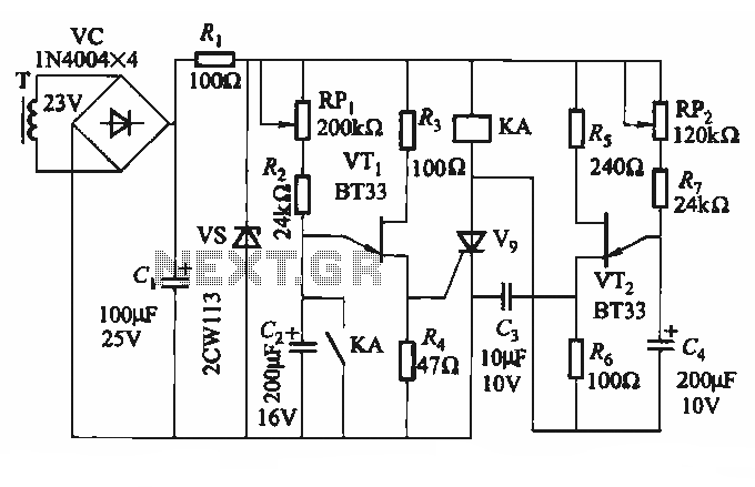
The circuit depicted in Figure 3-69 is designed for applications requiring frequent timing control for motor reversing operations. In this configuration, thyristors V1, V2, and V7 are utilized for positive control of motor rotation, while thyristors V3, V4, V5,...
This scheme is a Standing Wave Ratio (SWR) meter, which is relatively simple and can be easily constructed. Once a directional coupler is created, the results will be indicated on the measuring LED meters as a ratio of SWR. The...
The example below illustrates the use of an operational amplifier (op-amp) as an audio amplifier in a basic intercom system. A small 8-ohm speaker is utilized as a microphone, which is connected to the op-amp input through a 0.1...