
microcontroller Digital bargraph display driver circuit

To implement a digital-to-analog conversion suitable for driving the LM3914 bar graph display using the available digital outputs from the PIC16F84A, a resistor ladder network can be employed. This network will convert the digital signals into a corresponding voltage level that the LM3914 can interpret as an analog input.
The circuit can be designed using the following components:
1. **Resistor Ladder**: A series of resistors can be connected between the digital output pins of the MCU and ground. The values of the resistors will determine the voltage levels corresponding to different digital combinations of the output pins. For instance, using two digital pins can create four distinct voltage levels (00, 01, 10, 11) which can be translated into four different positions on the bar graph.
2. **LM3914 Configuration**: The LM3914 can be configured in bar mode to light up the appropriate number of segments based on the voltage input it receives from the resistor ladder. The reference voltage for the LM3914 can be set using a potentiometer connected to the V+ pin, allowing for adjustment of the maximum value displayed on the bar graph.
3. **Microcontroller Programming**: The PIC16F84A can be programmed to change the state of its output pins according to the desired progress level. By manipulating the two data pins, the MCU can create the necessary digital combinations that will result in the appropriate voltage levels at the output of the resistor ladder.
4. **Schematic Representation**: The schematic will consist of the PIC16F84A connected to two resistors forming a ladder network, which in turn connects to the input of the LM3914. The output of the LM3914 will drive the bar graph display directly.
This approach allows for effective use of the limited pins available on the microcontroller while ensuring that the bar graph display functions correctly without the need for additional costly components such as an IO expander. The resistor ladder configuration is a cost-effective solution for digital-to-analog conversion in this application.For a project I need to display a progress bar of the activity performed by my MCU. For this purpose I am going to use a bargraph display, but the problem is that bargraph display driver driver IC LM3914 uses analog input where as MCU produces a digital output. How can I display a value on bargraph using digital input instead of analog The bargra ph should display values from lower to higher and higher to lower. Schematics will be highly appreciated. I only have two data pins available on uC (PIC16F84a) to drive a Bargraph display, and IO expander will increase the cost of system. I tried IC 4017 for the purpose, but it provides only one ON pin at a time. 🔗 External reference
Related Circuits
The circuit is based on a single operational amplifier integrated circuit designed to produce a modular preamplifier that operates in Class A configuration. The modular preamplifier circuit utilizes a single operational amplifier (op-amp) integrated circuit, which serves as the primary...
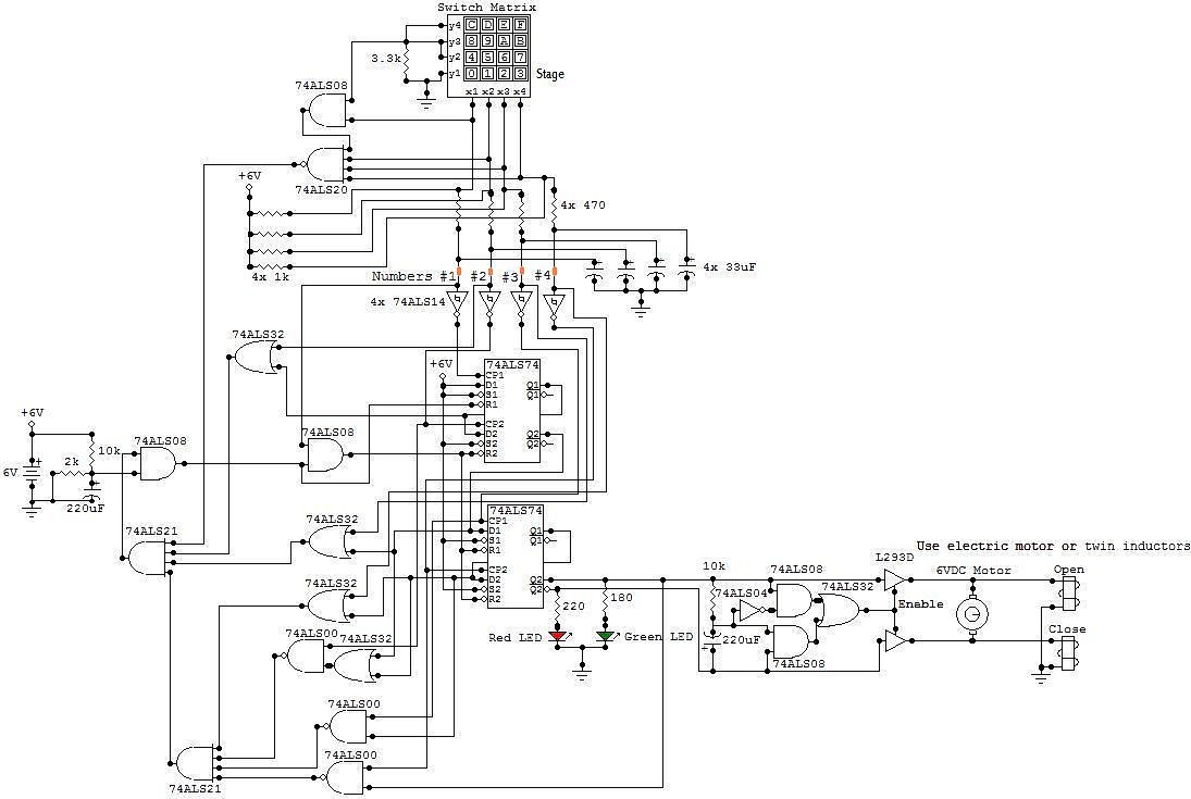
This circuit is an electronic locker controlled by a combination of switches (a code). It features a switch matrix located on the locker door, consisting of a unit of switches arranged in four rows and four columns, totaling eight...
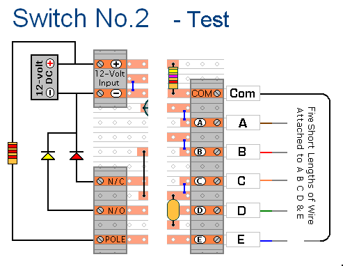
The prototype of Keypad Switch No. 2 was constructed using only the stripboard layout as a reference. If the layout has been accurately reproduced, a functional circuit will result. Once the layout is confirmed to be correct and a...
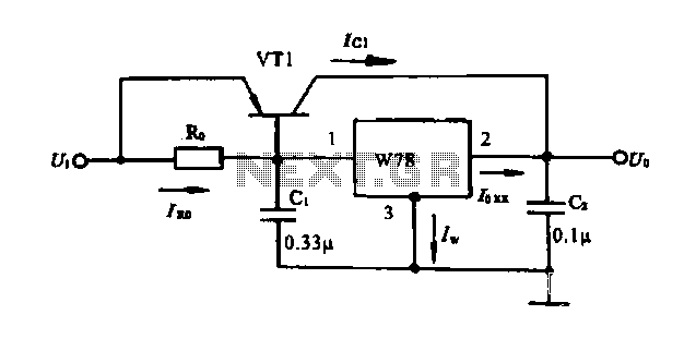
Extend the current application circuit. The maximum output current of the integrated three-terminal device in production is 1.5A. If the output current exceeds 1.5A, an external power transistor can be utilized to increase the output current, as illustrated in...
The bi-directional sequencer employs a 4-bit binary up/down counter (CD4516) and two "1 of 8 line decoders" (74HC138 or 74HCT138) to create the well-known "Night Rider" display. A Schmitt Trigger oscillator generates the clock signal for the counter, with...
Grounding the blue wire at the headlamp switch causes the lights to illuminate, indicating a faulty switch. Continuity of the switch has already been verified. The relay consists of two small terminals and two larger ones. The smaller terminal,...