
Microcontroller interface electrometer
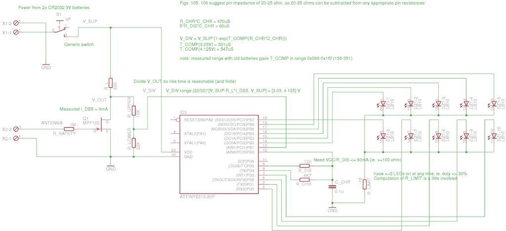
To create a static electricity measurement circuit, a simple design can be implemented using a high-impedance voltmeter or an analog meter. The circuit can be constructed using basic electronic components such as resistors, capacitors, and a sensitive meter.
The core of the circuit involves a high-value resistor, typically in the range of 1 MΩ to 10 MΩ, which is connected in parallel with the meter. This resistor allows the circuit to pick up small static charges without significantly discharging them. A capacitor can be added in parallel to the meter for smoothing the readings and preventing rapid fluctuations caused by transient static discharges.
To enhance the sensitivity of the measurement, a field-effect transistor (FET) can be incorporated. The FET acts as a high-impedance buffer, allowing the circuit to detect minute static charges. The gate of the FET can be connected to a conductive plate that collects static electricity from the surrounding environment.
The output from the meter can be calibrated to provide a readable voltage proportional to the static charge detected. Care should be taken to ensure that the circuit is properly shielded to avoid interference from external electromagnetic fields, which can affect the accuracy of the readings.
This circuit can serve as an educational tool for understanding static electricity and its measurement, providing practical experience in electronics for the student involved in the project.My daughter wanted a way of measuring static for her science project. While scanning through an old copy of Getting Started in Electronics by Forres.. 🔗 External reference
Related Circuits
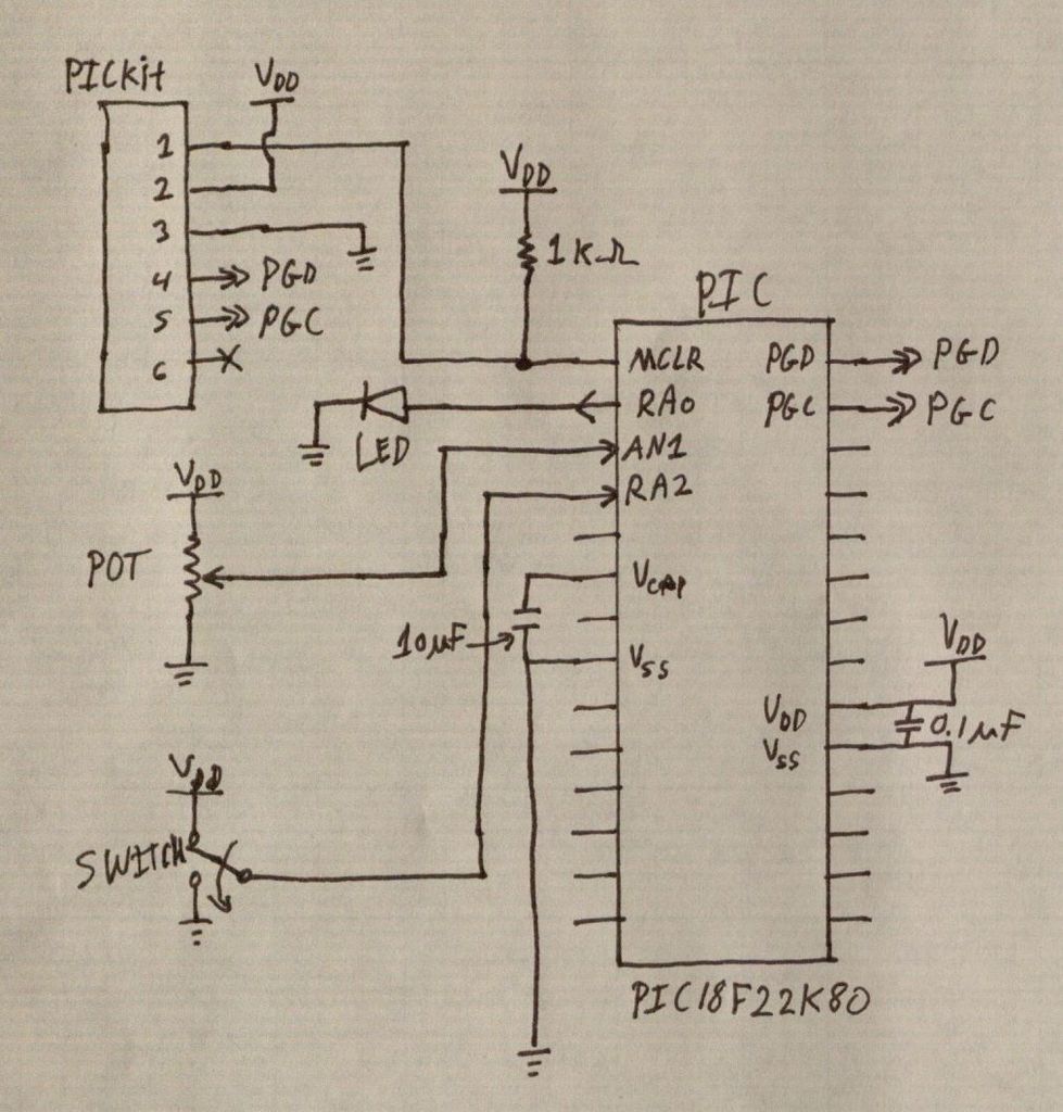
PIC microcontrollers are a highly useful and versatile component for various electronic projects. They are affordable and readily available. PIC microcontrollers are embedded systems that serve as the central control unit in a wide range of electronic applications. Their architecture...
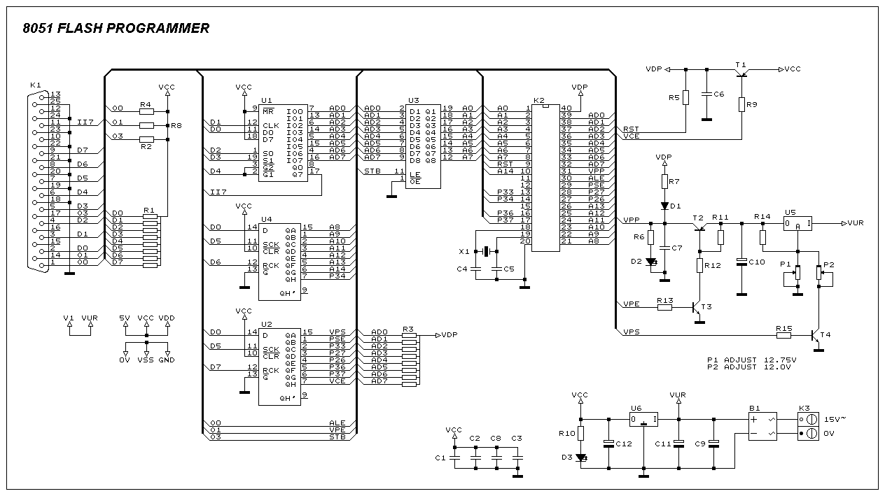
This programmer was designed to be flexible, economical, and easy to build. The programmer hardware utilizes standard TTL series parts, and no special components are used. The programmer is interfaced with the PC parallel port, and there are no...
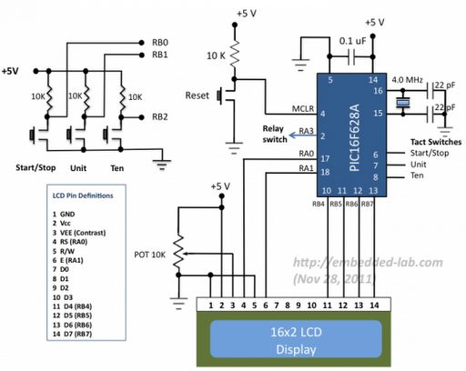
A source code for a simple PIC-based digital timer is provided. The hardware for the project is not available; however, it will be demonstrated using a DIY PIC16F628A breadboard module and I/O board. The complete circuit diagram and firmware...
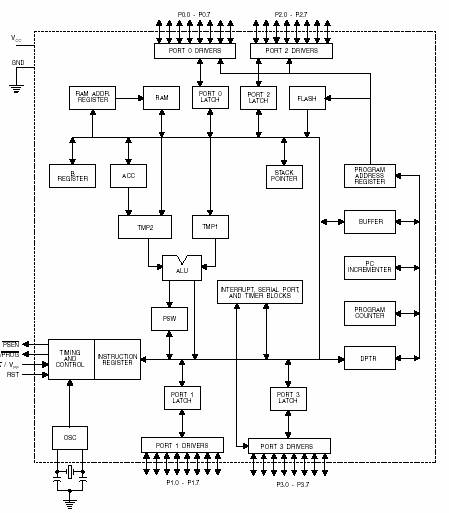
A microcontroller (MCU) is a compact computer integrated into a single circuit, comprising a relatively simple CPU along with supporting functions such as crystal oscillators, timers, sensors, and serial and analog input/output (I/O). Microcontrollers are designed for small-scale applications,...
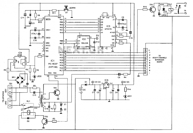
This device enables remote control of various appliances (up to eight with suitable add-on expansion boards) such as lights, water heaters, air conditioning, plant watering systems, alarms, etc., via a relay. It allows users to perform actions such as...
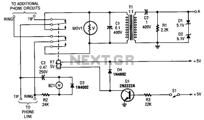
This circuit is designed for interfacing phone projects with the telephone line. It includes a ringer, has the capability to interrupt the wiring, and provides isolation for the project from the phone line. The circuit operates by integrating a ringer...