
Microcontroller Verification Password system

The described system utilizes an 8-bit password verification mechanism, which is fundamental in various security applications. The microcontroller plays a crucial role in this process, as it stores the actual password and executes the comparison logic. Upon receiving the user input, the microcontroller reads the 8-bit password and compares it against the stored password value using a binary comparison algorithm.
The comparison process involves checking each of the 8 bits of the entered password against the corresponding bits of the stored password. If all bits match, the microcontroller generates an 8-bit output signal indicating a successful verification. This output is connected to a logic circuit designed to interpret the result of the comparison.
The logic circuit may consist of basic logic gates such as AND, OR, and NOT gates, configured to produce a high output signal when the comparison result is positive. Specifically, if the output from the microcontroller indicates that the user-entered password matches the stored password, the logic circuit outputs a high signal, which can then be used to trigger subsequent actions, such as unlocking a device or granting access to a secure system.
In summary, this circuit design not only emphasizes the importance of secure password handling but also illustrates the integration of microcontroller functionalities with basic logic circuitry to achieve reliable password verification.An 8-bit password is the input to this system. The password entered by the user is compared with the actual password (password set in the microcontroller using the microprogram) by the microcontroller. The result of the comparison process is an 8-bit output at the output port, which is fed to a logic circuit.
If the user-password is correct, the o utput of the logic circuit will be high. 🔗 External reference
Related Circuits
The TRW-24G connector pins are quite small, approximately 1mm apart. To address this issue, an adaptor PCB has been ordered to convert the small connector of the RF module to a standard pin connector. The pin arrangement of the...
Nowadays every institution needs automation. As a part of college automation, a project has been developed for a Voice Interactive System for College Automation. This project allows users to quickly access student attendance and marks through the telephone line...
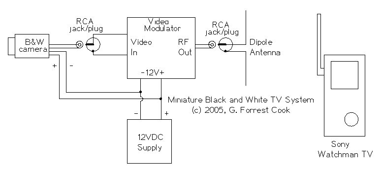
The 12VDC supply provides power for the camera and video modulator circuits. The video from the camera is fed into the video input of the modulator circuit. The modulated RF from the modulator is fed into a small antenna....
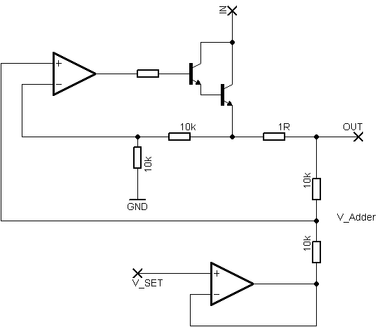
Rsense will cause Q2 to conduct when a threshold of approximately 0.65V is reached. Rbias will determine the extent of this limitation, although this aspect remains unclear. Particularly, if Rsense is positioned on the high side, simply activating Q2...
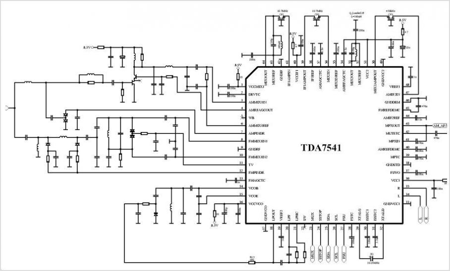
The TDA8340Q and TDA8341Q are integrated intermediate frequency (IF) amplifier and demodulator circuits designed for color and black-and-white television receivers. The TDA8340Q is intended for use with NPN tuners, while the TDA8341Q is suitable for PNP tuners. Both components...
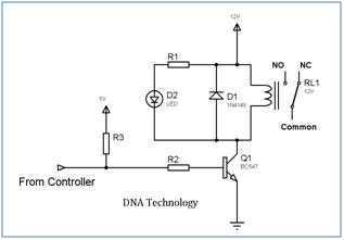
Relays are devices which allow low power circuits to switch a relatively high Current/Voltage ON/OFF. For a relay to operate a suitable pull-in & holding current should be passed through its coil. Generally relay coils are designed to operate...