
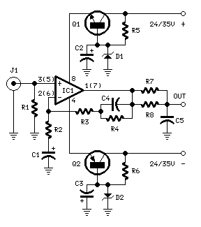
Microphone balanced preamplifier

The described circuit serves as a fundamental component of an audio mixing console, specifically designed to enhance sound quality by managing input signals from microphones or other high-level audio sources. It is modular in nature, allowing for scalability in channel count based on user requirements.
Key features of the circuit include phantom power, which provides necessary voltage to condenser microphones, ensuring optimal performance. The inclusion of reverse phase capability is crucial for eliminating phase cancellation issues that can arise when multiple audio sources are mixed. Signal attenuation is implemented to prevent distortion from excessively high input levels, thereby maintaining audio integrity. The gain control section allows for precise adjustment of channel levels, facilitating a balanced mix.
Components are chosen for their reliability and performance. Resistors with specified values, such as R1-2 at 6.8K ohm and R3 at 56K ohm, ensure proper signal routing and gain structure. Capacitors, including C1-2 at 33uF and C8-11 at 10uF, are essential for coupling and decoupling audio signals, as well as filtering out noise. The use of high-quality electrolytic and ceramic capacitors contributes to the overall sound fidelity.
Operational amplifiers like the NE5532 and TL072 are utilized for their low noise and high performance in audio applications, ensuring that the signal remains clean throughout processing. The circuit also incorporates metal film resistors with a tolerance of 1%, which are preferred for their stability and accuracy in audio signal processing.
The circuit's design anticipates integration with subsequent stages, such as a parametric equalizer, allowing for further manipulation of the audio signal. Careful consideration of component quality and layout is imperative to minimize interference and maintain signal clarity. This design approach ensures that the circuit not only meets but exceeds the expectations of professional audio applications. A professional suggestion for those interested in improving sound. The circuit constitutes the part of input mixing console sound from the microphone or source of high level . It can be used on it's own or be multiplied to the number of channels required. It includes all the useful functions such as, phantom power , reverse face, signal attenuation for avoiding distortions from high level signals regulating channel gains and the rest of the stages will be added next stages ,for full mixing console.
Attention must be paid to the quality of the materials used. This circuit may used, previous to Parametric EQ circuit. Part List R1-2= 6.8K ohm R16-19= 4.7Kohm C8-11= 10uF25V electrolytic R3= 56Kohm R17-18= 15Kohm C9-10= 47nF 63V MKT 5% R4-6= 2.2Kohm R20-21= 27Kohm C12-13= 47nF 63V ??? 5% R5-7= 220 ohm R22= 22Kohm T1-2= BC560C R8-9= 39Kohm R23-24-25= 47Kohm IC1= NE5532, TL072 R10-11= 2.7Kohm C1-2= 33uF 63V electrolytic S1-5= On/off Sw R12-13= 4.7Kohm C3-4= 680pf ceramic or mylar JF1-2= 3 pin-connector R14= 68 ohm C6= 100uF 25V electrolytic R15= 10Kohm log.
pot. C5-7= 120pF ceramic or mylar ?ll Registor is 1% metal film 🔗 External reference
Related Circuits
In recent years, following CD's introduction, vinyl recordings are almost disappeared. Nevertheless, a phono preamplifier is still useful for listening to old vinyl discs from a well-preserved collection. This simple but efficient circuit devised for cheap moving-magnet cartridges can be...
An electret microphone has been connected to an operational amplifier (op-amp), with the output directed to an Arduino microcontroller. The analog-to-digital converter (ADC) on the microcontroller converts a voltage range of 0 to 5 volts into a 10-bit number,...
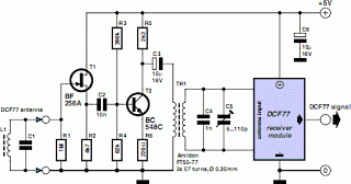
A popular project among microcontroller enthusiasts is to construct a radio-controlled clock. Compact receiver boards are available, equipped with a pre-tuned ferrite antenna, which can receive and demodulate the DCF77 time signal broadcast from Mainflingen, Germany. The DCF77 signal...
The M7 capsule features a center-terminated, dual-diaphragm design and supports three polar patterns. A switch on the power supply allows for the selection of Cardioid, Figure-of-8, or Omnidirectional patterns. The amplifier circuit is reminiscent of Gefell's historical models, the...
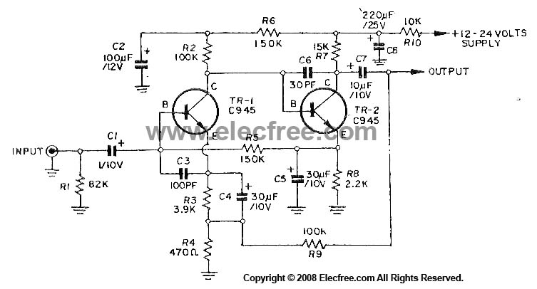
This circuit utilizes three transistors (2SC945, 2C1815, or 2SC828) as the primary components, functioning as a typical low-noise transistor amplifier. It offers a gain of approximately 200 to 300 times and has a frequency response ranging from 50Hz to...
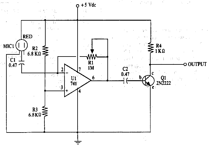
The amplifier features an adjustable gain, facilitated by R1, a 1 Mega Ohm variable resistor. This resistor regulates the feedback of the 741 operational amplifier (op-amp), which subsequently drives a 2N2222 output transistor. The circuit receives an audio signal...