
Audio Gambar Skema Condenser Microphone Amplifier
The described circuit employs a 741 operational amplifier due to its favorable characteristics for audio applications, including low noise and high input impedance. The variable resistor R1 allows for fine-tuning of the gain, making it possible to adapt the amplification level according to the requirements of the connected device. By adjusting R1, the feedback loop of the op-amp can be modified, which directly influences the overall gain of the amplifier.
The output stage of the circuit utilizes a 2N2222 transistor, a widely used NPN transistor known for its reliability and efficiency in switching and amplification applications. The transistor amplifies the output from the op-amp, providing sufficient current to drive devices that require higher signal levels than the microphone can provide.
The circuit is designed to interface with a condenser microphone, which typically outputs a very low-level audio signal. By amplifying this signal, the circuit allows the microphone to be connected to devices such as mixers, amplifiers, or recording equipment that may not be capable of processing such low-level signals. Careful consideration should be given to the power supply requirements of the op-amp and transistor to ensure stable operation, as well as the overall impedance matching to avoid signal loss. Proper bypass capacitors may also be included in the design to filter out noise and ensure clean signal transmission.The amplifier has an adjustable gain, which is performed by. R1 (a 1 Mega Ohm variable resistor). It controls the feedback of the 741 opamp, which in turn drive a 2N2222 output transistor. The circuit takes the audio signal rom the condenser microphone & amplifier it, so you are able to use the microphone as the input to some device which wouldn`t normally accept microphone level signals (which are very low). 🔗 External reference
Related Circuits
This is a simple circuit diagram for a 150W power amplifier. The circuit can be constructed without a printed circuit board (PCB). The power output ranges from 100W to 150W, depending on the power supply and the Darlington transistors...
This preamplifier has a low output impedance, and is designed to drive long cables, allowing you to listen to a remote music source without having to buy expensive screened cables. The very low output impedance of around 16 ohms...
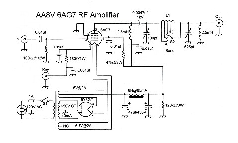
The input coupling capacitor allows the input signal to pass through to the grid of the tube while preventing the input source from potentially shorting the grid bias to ground. If the grid bias were shorted out, the 6AG7...
This mini audio amplifier will test the audio stages in amplifiers such as the front end of FM bugs. You can also use it on lots of our other projects as well as the output stages of radios. It...

This circuit is a robust and efficient power amplifier suitable for various audio applications. It delivers 60W RMS output at a 50V supply with an 8 Ohm load. The design is user-friendly, allowing for the use of non-critical components...
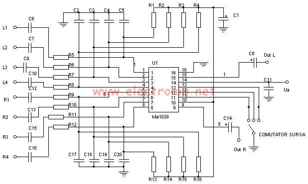
The TDA1029 is a dual operational amplifier configured as an impedance converter. Each amplifier features four mutually switchable inputs that are safeguarded by clamping diodes. Signal sources can be switched in various modes. The electronic components required for this...