
Microphone Preamplifier BC547B

This microphone preamplifier circuit is designed to interface dynamic and electret microphones with standard line-level audio inputs, making it suitable for various applications, including home audio systems and computer sound cards. The circuit employs a single transistor amplifier configuration to achieve a gain of approximately 30-40 dB, which can vary based on transistor characteristics, temperature, and supply voltage.
The design incorporates several key components: a 9V battery serves as the power source, consuming less than 10 mA, ensuring energy efficiency. The presence of an LED (D1) provides visual feedback that the circuit is powered and operational. The voltage drop across the LED, approximately 1.8V for a red LED, is accounted for in the circuit design to ensure proper biasing of the transistor (Q1).
Capacitors (C1, C2, C3) are strategically placed to block DC bias from the microphone inputs, allowing only AC signals to pass through to the transistor's base. Additionally, a filter composed of resistor R4 and capacitor C5 mitigates potential noise from the power supply, enhancing the overall sound quality of the output signal.
For the electret microphone input, resistor R1 is included to provide the necessary bias current, typically around 1 mA, required for the operation of the electret capsule's internal amplifier. The circuit is designed to accommodate typical low-cost electret microphones available in the market.
The physical construction of the circuit is recommended to be housed in a small metal enclosure, which aids in reducing external electromagnetic interference and noise. The enclosure should also accommodate the 9V battery, ensuring a compact and portable design. Input connectors consist of a 6.3 mm jack for dynamic microphones and a 3.5 mm mono jack for electret microphones, both accessible from the front panel, along with the LED indicator and power switch, facilitating ease of use.
This preamplifier circuit is characterized by its simplicity and effectiveness for casual audio applications, providing a reliable solution for interfacing microphones with audio equipment.This is a simple microphone preamplifier circuit which you can use between your microphone and stereo amplifier. This circuit amplifier microphone suitable for use with normal home stereo amplifier line/CD/aux/tape inputs.
This microphone preamplifier can take both dynamic and electret microphone inputs (preamplifier provides power foe electret microphone elements). The idea of this circuit is to keep the design as simple as possible to be easy to build. That was my goal when I needed a simple external microphone preamplifier for my mixer. The performance of the circuit is nothing superior but can be used with many not so serious projects.
Circuit performance: Amplification 35 dB, flat frequency response from 20 Hz to 20 kHz, quite poor distortion performance figures, a little bit noisy Availability of components: Uses common and easily available components Design testing: I have built few microphone preamplifiers based on this circuit and theu have worked without problems. Applications: Interface dynamic or electret microphone to a line level audio input in HIFI amplifier or computer soundcard.
Power supply: 9V battery, takes less than 10 mA current. The circuit is a simple one transistor amplifier with amplification of about 30-40 dB (depends on transitor, temperature and voltage). The dynamic mic input is just a simple one transistor amplifier circuit with nothing special in it. LED D1 is in the circuit to show that the circuit operates. The voltage drop caused by LED (around 1.8V for RED led) has been taten in account when designing the amplifier circuit built around Q1.
Resistor R4 and capacitor C5 make a filter to filter out possible noise from battery or other power source which is used to feed this circuit. Capacitors C1, C2 and C3 are used to block the DC bias on Q1 base to flow out of microphone input to microphone (the polarity of all capactors is straigh line = + and curved line = -).
The circuit is bet to build to a small metal box like in the picture above. Put the 9V battery inside the case too. Battery power and metal box keep external noise and interference sources away. I used standard 6.3 mm jack for dynamic microphone and 3.5 mm mono jack for electret micrphone both installed to from, panel of the metal box. The LED and power switches are also installed to front panel. Electret microphone input has a resistor R1 fo feeding current through electret microphone capsule when it is connected to the electret microphone input.
Electret microphone needs some current (about 1 mA) flowing through it to operate, because there is a small amplifier circuit inside the microphone capsule. This circuit is suitable for all typical cheap electret capsules which available from any electronic component shop.
Because electret microphones have higher signal level output, it is quite easy to overdrive the amplifier when you shout to electret microphone. 🔗 External reference
Related Circuits
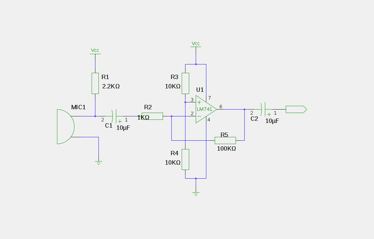
This is a good example preamplifier for microphones that can be used in mixing consoles. The circuit uses a dual op-amp, type NE 5532. The amplifier must be adjusted. This connect the power supply and control over P1 such...
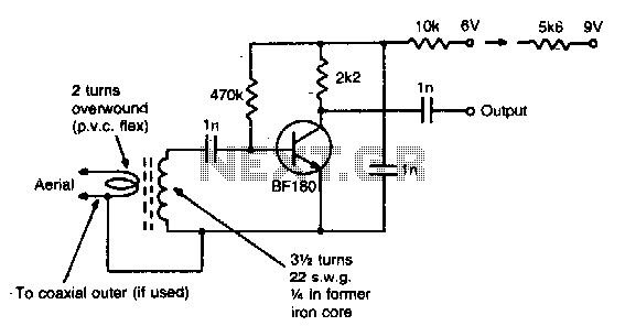
This simple circuit provides a gain of 15 dB and can be mounted on a 1 inch by 2 inch PCB. Coil specifications are provided for a frequency range of 85 to 95 MHz. For other frequencies, the coil...
An electret microphone has been connected to an operational amplifier (op-amp), with the output directed to an Arduino microcontroller. The analog-to-digital converter (ADC) on the microcontroller converts a voltage range of 0 to 5 volts into a 10-bit number,...
A simple yet effective amplifier unit characterized by low distortion. A similar modification was employed in the HAFLER preamplifier. The quality of the reproduced sound in all symmetrical amplifiers remains consistent, regardless of the cost of materials, including transistors,...
This module is an essential addition to the Modular Preamplifier Control Center when more than two sources need to be connected to the preamplifier chain. Four high-level inputs can be selected using SW1 and routed to the output. The...
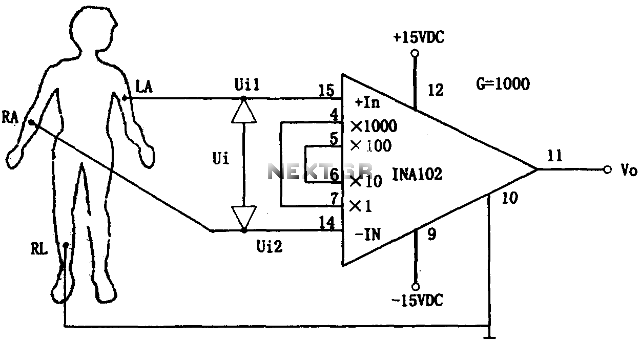
This document outlines a preamplifier circuit designed for measuring human biological signals, such as ECG and EEG. These biological signals are typically weak and require high amplification circuits. The circuit utilizes a low-power integrated operational amplifier, INA102. The INA102...