
Vhf preamplifier

The circuit in question is designed to amplify signals with a specified gain of 15 dB, making it suitable for applications requiring moderate signal enhancement. The compact size of the PCB, measuring 1 inch by 2 inches, allows for easy integration into various electronic devices and systems.
The core component of this circuit is the coil, which is critical for tuning the circuit to the desired frequency range of 85 to 95 MHz. The coil's inductance and the circuit's associated capacitive elements determine the resonant frequency. For operation outside this specified range, adjustments to the coil's inductance or the addition of capacitive components may be necessary to achieve optimal performance.
In practical applications, this circuit can be employed in RF (radio frequency) amplification tasks, such as in transmitters or receivers where signal strength needs to be improved without introducing significant noise. It is essential to ensure that the components used are rated for the expected frequencies and power levels to maintain circuit integrity and performance.
Furthermore, careful consideration should be given to layout and grounding on the PCB to minimize parasitic capacitance and inductance, which could affect the circuit's performance at higher frequencies. Proper shielding may also be implemented to prevent interference from external signals, ensuring that the gain remains consistent across the specified frequency range.
Overall, this circuit is a versatile solution for RF amplification needs, with the flexibility to be adapted for various frequency requirements through coil modification.This simple circuit gives 15 dB gain and can be mounted on 1 in 2PCB. Coil data is given for 85 to 95 MHz For other frequencies modify coil as required.
Related Circuits
Although many album titles that were once available on vinyl are gradually being released on CDs, not all titles are accessible. It is possible that there are valuable records in a collection that one might wish to convert to...
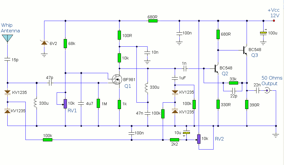
The antenna amplifier circuit comprises approximately 40 components, featuring two NPN transistors (BC548), one MOSFET (BF981), two varicap diodes (KV1235), and a 6.2V zener diode. It includes a 330µH inductor/coil, which can be modified for operation on different frequency...
Once again my collection of projects creation has been interrupted by another necessity. Patrick and other people have asked me for a circuit of a VHF power amplifier. These circuits are my "standard" building blocks that can be used...
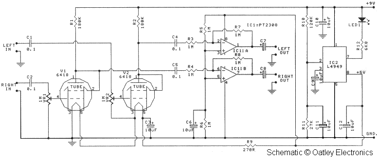
Oatley Electronics, located in New South Wales, Australia, offers several kits based on the Raytheon JAN 6418 sub-miniature valve (tube). The K272A Stereo Tube Preamplifier - Headphone Driver kit, priced at $27 AU, is one such kit. (Note: The...
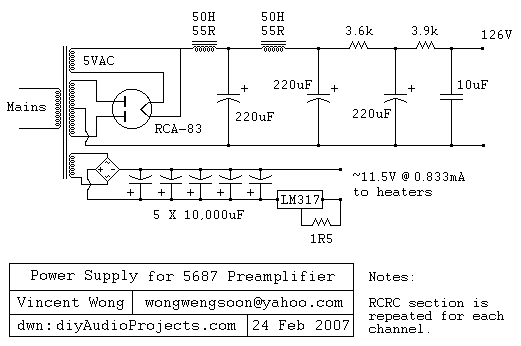
The RCA-83 rectifier utilizes 5VAC for the filament supply. The heaters for the 5687 tubes are powered by a full bridge rectifier consisting of MUR860 diodes, followed by five 10,000µF Elna capacitors. Current regulation is achieved through an LM317...
A Darlington transistor can enhance circuit performance, although it introduces slight complexity. The advantage of using a Darlington configuration lies in its capability to achieve low output impedance. The recommended component is the 2N6426 from Mouser, with alternatives such...