
Micropower battery splitter

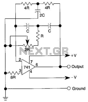
The described circuit functions as a voltage divider and inverter, producing dual output voltages that are symmetrical around a common reference point. The configuration typically involves operational amplifiers (op-amps) or a dedicated voltage inverter IC. The input voltage, which can be supplied by a single battery, is divided to create two output voltages: +Vout and -Vout, each at half the input voltage level.
In practical applications, when using a 9-V battery, the circuit generates +4.5 V and -4.5 V outputs. The reference point at pin 3 is crucial as it establishes a ground level for both output voltages, ensuring that the circuit can interface with other components effectively.
When the input voltage exceeds 6 V, the requirement to connect pin 6 to pin 3 ensures stability and proper operation of the circuit. This connection helps to maintain the integrity of the output voltages by providing a consistent reference point, preventing potential issues related to voltage fluctuations or unbalanced outputs.
The design can be implemented on a breadboard for prototyping or as a printed circuit board (PCB) for more permanent installations. Careful consideration should be given to the choice of components, including resistors and capacitors, to optimize performance and minimize noise in the output signals. Proper bypass capacitors should be employed near the power supply pins of the op-amps to ensure stable operation under varying load conditions.
Overall, this circuit is versatile and can be adapted for various applications requiring dual voltage supplies, such as powering analog sensors or operational amplifiers that require dual polarity supplies for signal processing.This circuit provides symmetrical ±output voltages, both equal to one-half the input voltage (one 9-V battery in this case). The output voltages are referenced to pin 3 (output common). The circuit will operate with other battery voltages. If the battery exceeds 6 V, pin 6 should also be connected to pin 3, as shown by the dashed line. 🔗 External reference
Related Circuits
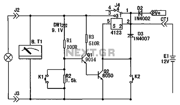
The circuit depicted in the figure consists of a battery, a controller, and various electrical and charging components. It includes a Zener diode (D1) and resistors (R1, R2) for undervoltage detection. The circuit also features transistors (Q1, Q2), resistors...
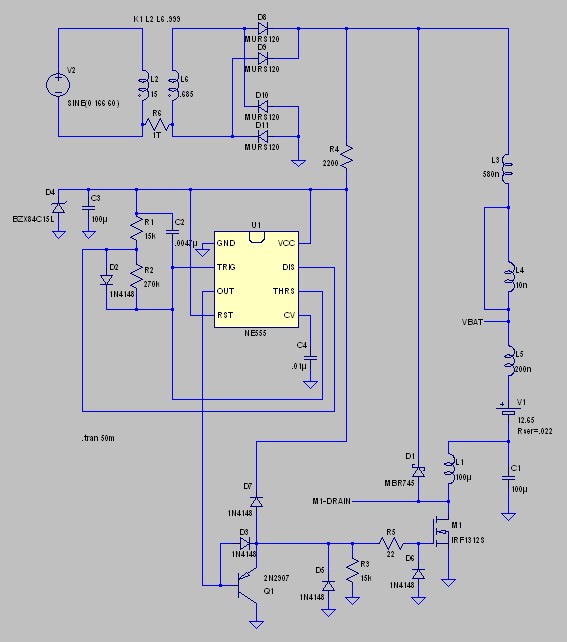
Desulfation is the process of reversing sulfation that occurs in a lead-acid battery over time. Desulfation partially restores the battery's ability to hold a charge, which is diminished due to sulfation. Desulfation is a critical maintenance procedure for lead-acid batteries,...

A simple battery charger circuit with reverse polarity indication is presented. The circuit utilizes the L200 integrated circuit, which is a five-pin variable voltage regulator. It can be powered by DC voltage from either a bridge rectifier or a...
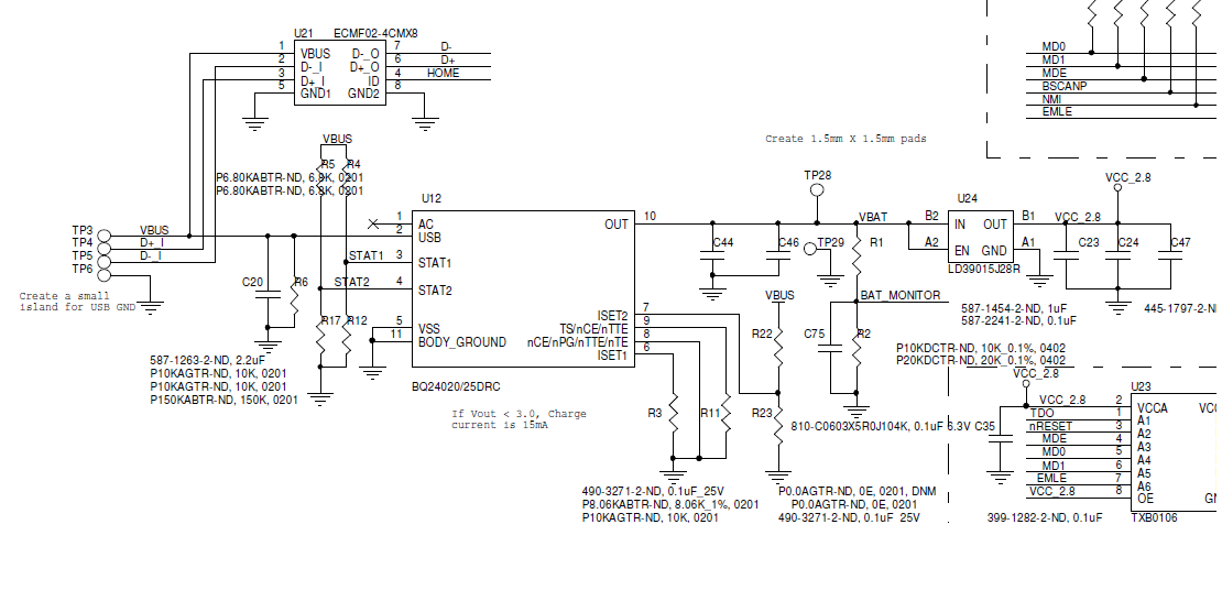
A BQ24020 charger IC is being utilized to charge a 120mAh Li-ion battery with a set charge current of approximately 100mA. The circuit schematic has been provided. The issue encountered is that the STAT1 and STAT2 signals indicate the...
The quality of the sine wave depends on how closely the components in the twin-T network are matched in the operational amplifier's feedback loop. The twin-T network is a type of filter circuit commonly used in audio applications, signal processing,...
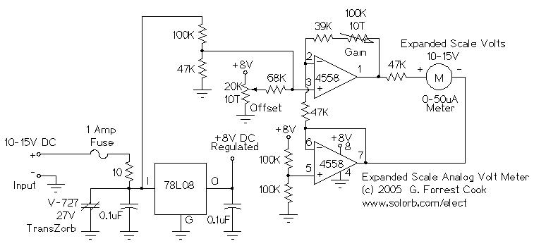
This circuit is designed to measure the voltage of a 12V nominal lead-acid rechargeable battery system. While it was specifically created for solar-powered systems, it is versatile enough for use in automotive or other 12V applications. Lead-acid batteries typically...