
Battery Powered Sine Wave Generator Circuit

The twin-T network is a type of filter circuit commonly used in audio applications, signal processing, and waveform generation. It consists of two resistive-capacitive (RC) networks arranged in a T configuration, which allows for the selective attenuation of certain frequencies while passing others. The twin-T network is particularly effective for generating sine waves due to its ability to produce a narrow bandpass response.
In this configuration, the operational amplifier (op-amp) plays a crucial role in determining the overall performance of the sine wave output. The feedback loop of the op-amp is where the twin-T network is integrated, and the quality of the sine wave produced is heavily influenced by the matching of the components within this network.
To achieve a high-quality sine wave, it is essential that the resistors and capacitors used in the twin-T configuration are closely matched in terms of their values. Component tolerances can introduce distortions and affect the frequency response, leading to deviations from the ideal sine wave. Therefore, using precision components with low tolerance values is recommended to ensure that the network maintains its intended characteristics.
The twin-T network typically consists of two resistors and two capacitors, with the output taken from the junction between the two capacitors. The values of these components can be calculated to set the desired frequency of oscillation. The op-amp, configured in an inverting or non-inverting mode, amplifies the signal coming from the twin-T network, ensuring that the output sine wave is of sufficient amplitude for the intended application.
In summary, the quality of the sine wave generated by a twin-T network in an op-amp feedback loop is significantly influenced by the precision matching of its components. Careful selection and calibration of resistors and capacitors are vital for achieving a clean and stable sine wave output, making this configuration a popular choice in various electronic applications. The quality of the sine wave depends on how closely you match the components in the twin-T network in the op amp`s feedback loop.
Related Circuits
The following circuit illustrates a LEGO Light Sensor Circuit Diagram. This circuit is based on the LM358 integrated circuit, which features a dual operational amplifier and high-speed capabilities. The LEGO Light Sensor Circuit utilizes the LM358, a versatile dual op-amp...
The circuit consists of inverter and charger sections. The inverter section utilizes the NE555 timer, while the charger section is based on the LM317 adjustable regulator. In the inverter section, the NE555 is configured as an astable multivibrator, generating...
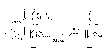
To control a stepper motor, each winding must be energized individually in a specific and timed sequence. This energization is carried out by a driver circuit, which acts as an amplifier. The timing is managed by an indexer circuit,...
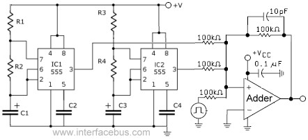
This circuit combines the outputs from two distinct 555 multivibrators using a summing operational amplifier (Op Amp). It serves to illustrate an alternative implementation of a 555 timer, with most background calculations addressed in other sections. The standard configuration...
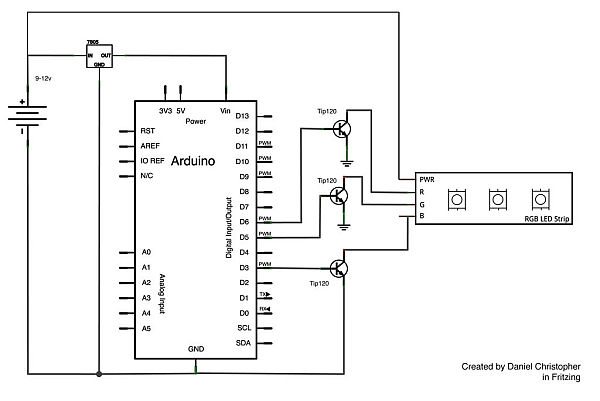
This document outlines the assembly of a circuit designed to pulse width modulate (PWM) a high-power RGB LED strip and program an Arduino to cycle through various colors. The term "high power" refers to a voltage range of 9-12...
The objective is to enhance information transmission through the distribution of articles. Please contact us via email at [email protected] within 15 days if there are any issues related to article content, copyright, or other concerns. Prompt deletion will occur...