
SIMPLE TLO82 VCO
The described voltage-controlled oscillator (VCO) circuit employs the TL082, which is a low-noise JFET-input operational amplifier known for its high input impedance and low offset voltage. The VCO's output frequency is modulated by an input control voltage, allowing for precise frequency tuning across the specified range.
In this configuration, the TL082 operates in an astable multivibrator mode, where the frequency of oscillation is determined by external resistors and capacitors connected to its inverting and non-inverting inputs. The feedback network is crucial in establishing the timing characteristics of the oscillation, typically involving resistors that set the charge and discharge times of the timing capacitor.
The relationship between the control voltage and the output frequency is linear within the specified range, providing a predictable response suitable for applications such as signal generation, modulation, and frequency synthesis. The circuit may include additional components such as diodes for temperature compensation or filtering capacitors to stabilize the output signal and reduce noise.
To ensure optimal performance, careful selection of the component values is necessary, taking into account the desired frequency range and the characteristics of the TL082. Furthermore, proper power supply decoupling should be implemented to minimize noise and enhance the stability of the oscillator.
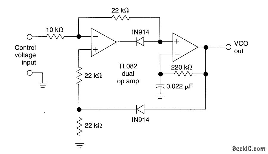
Overall, this voltage-controlled oscillator circuit is versatile and can be adapted for various applications in electronic systems requiring frequency modulation or signal generation.This circuit uses a dual operational amplifier (TL082) to form a voltage-controlled oscillator (VCO). With the component values shown, the output-frequency range is 100 Hz to 10 kHz when the input control voltage is between 0.
05 and 10 V. 🔗 External reference
Related Circuits

This circuit is sensitive to low-frequency electromagnetic radiation and can detect hidden wiring or the field surrounding a transformer. A radial type inductor is used as a probe, which effectively responds to low-frequency changing magnetic and electric fields. Ordinary...
The circuit biases the BC558 transistor, causing LED D1 to flash in response to signals from the remote control. The preset resistor in the circuit sets the sensitivity level. The circuit utilizes a BC558 PNP transistor, which plays a crucial...
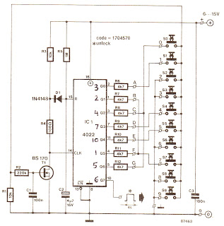
The cycle is repeated only when the S7 switch at the Q1 output is pressed within the designated time frame. When all keys are pressed in the correct order and within the specified time, Q7 goes high for approximately...
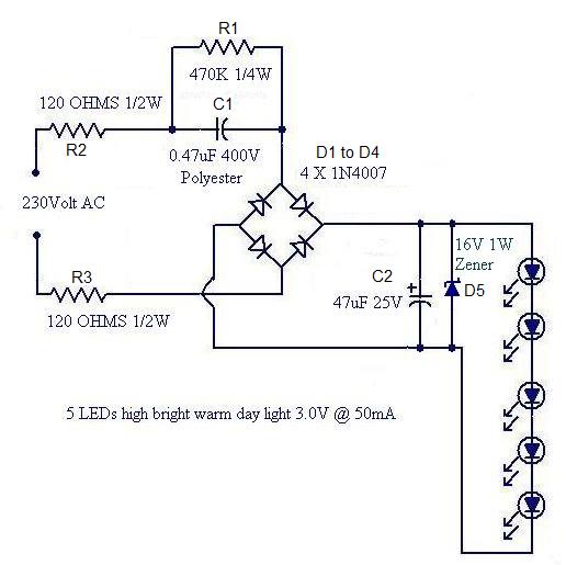
Convert a used CFL into a power-saving LED lamp circuit that consumes only 50mA. This gadget can be used in applications like a night light, table lamp, etc. The project involves redesigning a compact fluorescent lamp (CFL) to function as...
You need a power supply for a project, but only have a DC adapter available, so you can't use my AC power adapter trick (Project 05). This little project came about because a reader had just this problem, and...
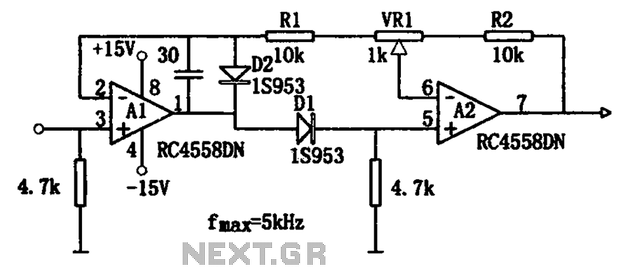
The circuit illustrates a simple method for adjusting the high input impedance of a double wave linear detector. It employs an operational amplifier configured with a negative feedback loop to compensate for the non-linear behavior of the diode used...