
Microprocessor power supply watchdog
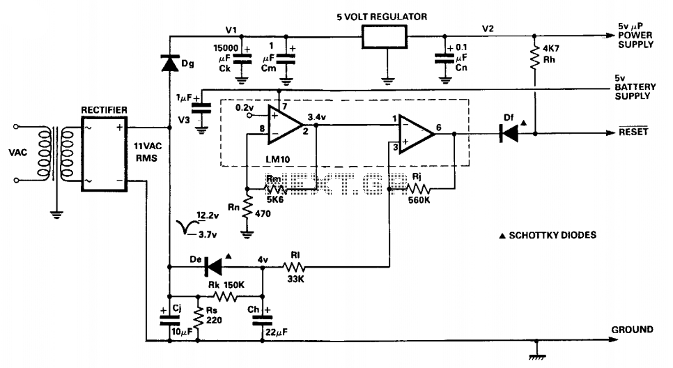
The circuit is designed to ensure reliable operation of the microprocessor by monitoring the regulated 5 V supply. The full-wave bridge rectifier converts AC voltage to DC voltage, which is then smoothed by the resistor-capacitor network formed by Rs and Cj. This network produces a triangular waveform that fluctuates with the supply voltage. The characteristics of this waveform are critical, as the lowest point of the triangular wave is used to determine when the voltage has dropped below an acceptable level.
The LM10C voltage reference provides a stable reference against which the triangular waveform is compared. The feedback network composed of resistors Rn and Rm is configured to establish a threshold voltage of 3.4 volts, which is set to 90% of the minimum voltage of the triangular waveform. This ensures that the reset condition is triggered with a margin, preventing premature resets during normal operation.
When the voltage at the non-inverting input of the comparator dips below this threshold, the comparator output transitions to a low state. This output is connected to the reset pin of the microprocessor, effectively resetting it to prevent erratic behavior caused by inadequate supply voltage.
Capacitor Ch plays a crucial role in the reset timing. It charges slowly through resistor Rk, allowing a delay in the reset signal, which provides time for the supply voltage to stabilize. Once the reset condition is triggered, capacitor Ch discharges quickly through diode De, ensuring a rapid reset of the microprocessor. The inclusion of diode Dg in the circuit prevents unwanted interactions between capacitors Cj and Ck, maintaining the integrity of the voltage monitoring function.
Overall, this circuit is essential for maintaining the stability and reliability of the microprocessor in environments where supply voltage fluctuations may occur. By implementing a well-designed voltage monitoring and reset circuit, the risk of microprocessor failure due to voltage drops is significantly reduced.The circuit monitors the input to the microprocessor 5 V regulated supply for voltage drops and initiates a reset sequence before supply regulation is lost. In operation, the resistor capacitor combination Rs and Cj form a short time constant smoothing network for the output of the fullwave bridge rectifier.
An approximately triangular, voltage waveform appears across C and Rs and it is the minimum excursion of this that initiates the reset. Diode Dg prevents charge sharing between capacitors Cj and Ck. Resistors Rn and Rm form a feedback network around the voltage reference section of the LM10C, setting a threshold voltage of 3.4 volts.
The threshold voltage is set at 90% of the minimum voltage of the triangular waveform. When the triangular wave trough, at the comparator's non-inverting input, dips below the threshold, the comparator output is driven low. This presents a reset to the microprocessor. Capacitor Ch is charged slowly through resistor Rk and discharged rapidly through diode De. 🔗 External reference
Related Circuits
An emergency light system utilizing white LEDs, which provides several advantages: 1. It is highly bright due to the use of white LEDs. 2. The light activates automatically during a mains power failure and deactivates when mains power is...
The Cockcroft-Walton multiplier employs a series of diodes and capacitors arranged in a cascade to generate a high-voltage DC potential from an AC input. This circuit topology utilizes diodes to charge capacitors in parallel and discharge them in series....
Switch on one unit, and everything else you need turns on automatically. This can save the tedium of turning on half a dozen different things, when one should be enough! This is another project created purely from necessity. In...
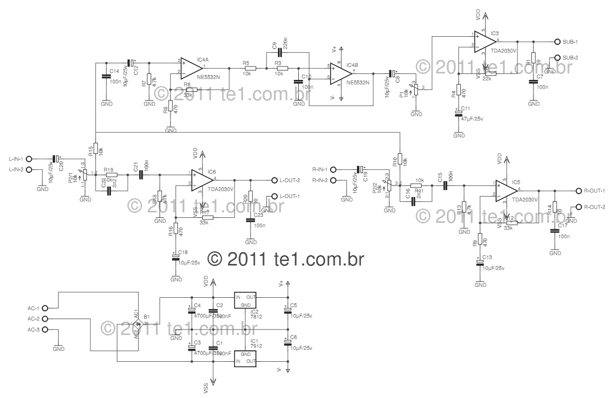
This circuit is a complete application for a 2.1 amplifier system, featuring two satellite speakers for TDA and one subwoofer. It is commonly used in commercial applications to enhance the audio output of computers using a stereo amplifier along...
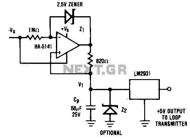
It is generally advantageous for the remote transmitter of a 4 to 20 mA current loop system to be powered directly from the transmission line. However, in certain scenarios, high power demands of the remote sensor/transmitter system may preclude...
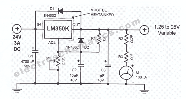
This regulated power supply is adjustable between a few volts and 15V using P1, while P2 is used to set the upper limit at 15.0V. The value of R6 is calculated as 0.7V divided by Imax, where Imax represents...
Warning: include(partials/cookie-banner.php): Failed to open stream: Permission denied in /var/www/html/nextgr/view-circuit.php on line 713
Warning: include(): Failed opening 'partials/cookie-banner.php' for inclusion (include_path='.:/usr/share/php') in /var/www/html/nextgr/view-circuit.php on line 713