
mid position valve

The three-port valve circuit operates with a combination of mechanical and electronic components to facilitate efficient heating and hot water management within a central heating system. The AC motor is responsible for moving the valve between positions A, B, and A+B, controlled by the micro-switches that act as position sensors. The configuration of the micro-switches is critical, as they provide feedback to ensure the motor is powered correctly based on the valve's position. The resistor and diode work together to convert AC to DC, allowing the motor to hold its position when required while minimizing the risk of overheating and burnout.
In operation, when the system calls for heating, the white wire is energized, activating the motor to open port A. The interaction between the spring and motor is vital for smooth operation, as the spring provides the necessary force to return the valve to its resting position when the motor is deactivated. The valve's design, featuring a rubber ball, allows for minimal friction and wear, enhancing longevity and reliability. Regular maintenance, such as applying silicone grease, is recommended to prevent stiffness and ensure optimal performance.
The circuit's design must also account for safety features, such as the ability to cut power to the motor if it is stalled in an undesirable position, preventing damage and ensuring the system operates safely. Overall, the three-port valve is an essential component of central heating systems, allowing for efficient management of heating and hot water distribution.The three port valve is a masterpiece of clever engineering, in that it manages to move to one of three positions using only a cheap non-reversible AC motor, a spring, a couple of micro-switches, a resistor and a diode, and act as a relay for the boiler into the bargain! However, it has obviously required quite a bit of lateral thinking to conjure up, and its operation is thus not easy to understand. Here`s how it works. The spring pulls the valve to open the flow through port B (traditionally connected to the hot water cylinder`s heating coil), while the motor winds it towards opening port A (feeding the radiator circuit). If the motor is left continuously powered, it will stall in with port A open, but if it is fed with DC (produced with the resistor and the diode), then it will stall in any position.
Two micro-switches, operating just either side of the `A+B` point, are used to define this position. The switches SW1 and SW2 are shown in the valve rest position (port B open). As the valve moves over towards the A position, SW1 changes over just before the A+B point, and SW2 just after. The white and grey wires are the control inputs, the orange is the output to the boiler for port A open, and blue is neutral.
In the central heating and hot water "both off" state, the system wiring results in grey being live. If the valve happens to be in the A+B or A port open position, SW1 will have been operated, the motor will be fed with AC, and the valve will wind to open port A and stay there (although the orange boiler output will not be live). This is a fly in the ointment for this valve configuration: the motor can be left consuming power and wearing out its hot windings unnecessarily (the spec says the valve consumes 6W).
This will not happen in the summer though, when heating is never selected: SW1 will be at rest, and the valve will sit un-energised with port B open. The 270K resistor supplies a small AC current to de-magnetise the motor from the effects of the rectified DC that is used to hold it in the mid-position.
Without this, there is some risk that the return spring will not be able to overcome the residual magnetic stiction to return it to the end position. In the "water and heating" state, white is energised. If the valve has port B open, the motor will wind it until A+B, whereupon SW1 changes over, DC is applied to the motor via SW2, and it will stall.
If it overshoots, or if it port A was open, SW2 will be operated as well, removing all power from the motor, and allowing the spring to pull the valve back to A+B. It is fun to watch this happening: as the spring pulls the valve back from A open to A+B, the motor acquires quite a momentum and overshoots.
It then winds forward a little, and stops in the correct position. In the "heating only" state, both white and grey are energised (hence the need for a changeover tank stat, and a "hot water not required" output from the programmer). Regardless of the position of either switch, AC will be supplied to the motor, and it will wind to open port A.
In addition, SW2 will connect white to orange, switching on the boiler. (The boiler is switched externally to the valve in the other situations. ) As has already been mentioned, a common failure mode is the motor burning out: hence the provision of replaceable heads. In this case, the valve will sit in port B open position and the motor will be cold. The valve can also stiffen up, if water gets in between the two O-rings that seal the actuating shaft.
This will manifest itself as the valve sitting in a random position, or in position B but with a hot motor. Applying silicone grease to the operating shaft can cure this: the heating will need to be drained, the valve head and cover removed, and a cir-clip taken off the shaft.
The actual valve consists of a freely-rotating rubber ball which is swung on an arm between the two ports. For more on central heating valves fo all 🔗 External reference
Related Circuits
Instructions for constructing a MIDI interface that connects a Sound Blaster (SB), Sound Blaster Pro (SB Pro), or Sound Blaster 16 (SB16) sound card joystick port to a MIDI-capable musical instrument. To build a MIDI interface for connecting a Sound...
The congestion of the ether is increasing, prompting ongoing efforts to extend communication channels to higher frequencies. Wavelengths as short as 12 meters are now common, but operating below this presents significant challenges. At approximately one meter, the oscillation...

The primary function of this circuit is to activate a buzzer or a relay whenever the humidity level reaches a specified threshold. The main component is a memory element based on a flip-flop made up of gates and integrated...
This pyrometer is used to measure the temperature of an incandescent body. The principle behind this measurement is that the hotter the body, the spectrum of the emitted radiation will shift. A pyrometer is a non-contact temperature measurement device that...
This device supports up to 8 analog inputs with a voltage range of 0 to 5 volts, generating selectable MIDI control output commands. The analog inputs can include rotary or slider potentiometers connected to the 0 to 5 volts...
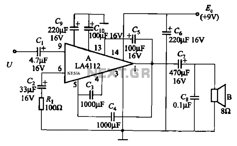
Audio power amplifier circuit utilizing the LA4112 integrated power amplifier along with additional components as shown in the figure. The audio power amplifier circuit based on the LA4112 integrated power amplifier is designed to deliver high-quality audio amplification for various...