
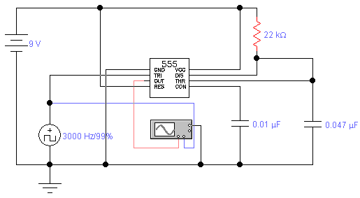
10Khz oscillator

In this circuit, the operation begins with the capacitor charging to a predetermined switching voltage. This voltage is critical as it determines when the switch (SUS) will activate. Upon reaching this voltage threshold, the SUS switch closes, allowing current to flow through the inductor. The inductor, due to its property of opposing changes in current, causes the current to oscillate or "ring." This oscillation is a result of the energy stored in the inductor being released and then reabsorbed in the circuit.
As the current continues to flow, it eventually decreases. The point at which this current falls below a specific value known as the holding current is essential for the operation of the circuit. Once this threshold is crossed, the SUS switch turns off, interrupting the current flow. This cessation of current causes the capacitor to begin charging again, thus restarting the cycle.
This repeating cycle of charging, switching, and discharging is fundamental in various applications, such as in power converters or oscillators, where controlled energy transfer is necessary. The precise values of the capacitor, inductor, and the defined switching and holding currents are crucial for the stability and efficiency of the circuit's operation. Proper selection of these components ensures that the desired performance characteristics are achieved, contributing to the overall functionality of the electronic system.The capacitor charges until switching voltage is reached. When SUS switches on, the inductor causes current to ring When the current thru SUS drops below the holding current, the device turns off and the cycle repeats.
Related Circuits
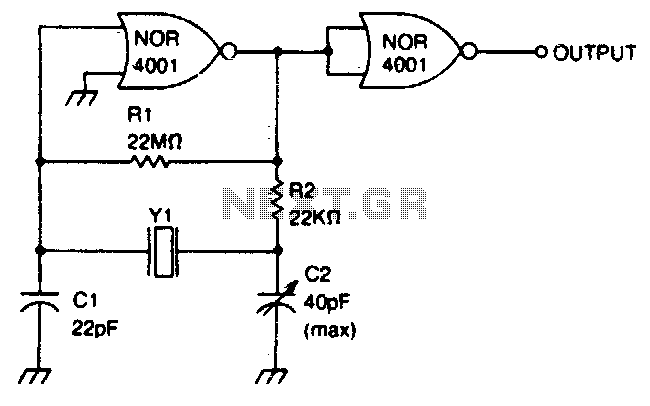
This circuit operates within a frequency range of 0 MHz to 2 MHz. The frequency can be finely adjusted to a specific value using the trimmer capacitor C2. Additionally, the second NOR gate functions as an output buffer. The circuit...
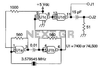
A circuit utilizing one 7400 TTL can operate with fundamental type crystals ranging from 1 to approximately 13 MHz. The output is rich in harmonics, making this oscillator suitable for calibration and testing applications. The circuit in question employs a...
A simple variable frequency oscillator utilizing a 555 timer IC to generate a square wave frequency that can be adjusted using a potentiometer. The circuit operates primarily on the principles of astable multivibrator configuration using the 555 timer IC, which...
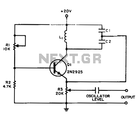
The Colpitts sinusoidal oscillator offers stable output amplitude and frequency ranging from 0°F to +150°F. It delivers a large output amplitude with low harmonic distortion. Oscillation is maintained through feedback from the collector tank circuit to the emitter. The...
The standard assumption is that the phase shift sections operate independently. According to the equation provided, the loop phase shift reaches -180 degrees when the phase shift of each section is 60 degrees. This condition is met when ω...
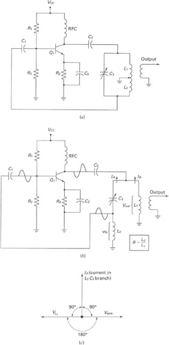
A widely recognized circuit is the Hartley oscillator, which is characterized by a tapped coil within the LC tank circuit. The tap point of the coil is grounded. The oscillator's amplifier section functions as a common-emitter amplifier, resulting in...