
mini audio analyzer

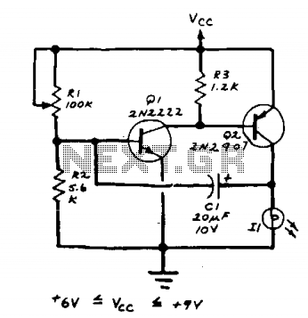
The circuit described operates as an acoustic signal analyzer, utilizing an LED as a visual output to represent the characteristics of the incoming signal. The core components of the circuit include a microphone or piezoelectric sensor to capture the acoustic signals, an analog-to-digital converter (ADC) for digital signal processing, and a microcontroller to interpret the signal data.
The microphone converts sound waves into electrical signals, which are then fed into the ADC. The ADC samples the analog signal and converts it into a digital format that can be processed by the microcontroller. The microcontroller analyzes the digital signal to determine both the frequency and the width of the signal.
To represent the signal width, the microcontroller adjusts the brightness of the LED. This is achieved through pulse-width modulation (PWM), where the duty cycle of the PWM signal controls the average power delivered to the LED. A wider signal translates to a higher duty cycle, resulting in increased brightness.
For frequency representation, the microcontroller may use a color LED or a multi-color LED that can change color based on the frequency detected. By mapping specific frequency ranges to corresponding colors, the system provides a visual representation of the frequency content of the acoustic signal.
This circuit can have applications in various fields such as audio engineering, sound analysis, and educational tools for demonstrating acoustic principles. Proper calibration and tuning of the circuit are essential to ensure accurate representation of the signal characteristics, which can be achieved through adjustments in the software algorithms and hardware components.This analyst is, a sensitive instrument, in the frequency changes and width of a acoustic signal. Thus the brightness of LED that turns on each moment of is proportional signal width, while the colour of proportionally frequency.. 🔗 External reference
Related Circuits
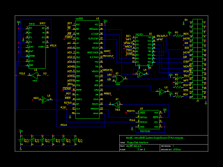
The initial version of the schematics has been completed. There remain several optimizations to be made, particularly concerning the logic gates. The resistors connected directly to the 8085 microprocessor are not strictly necessary, but they may be useful for...
The lamp should be a No. 122, No. 222, or other similar miniature incandescent lamp. R1 adjusts the flash rate. The circuit incorporates a miniature incandescent lamp, specifically a No. 122 or No. 222 type, which serves as the primary...
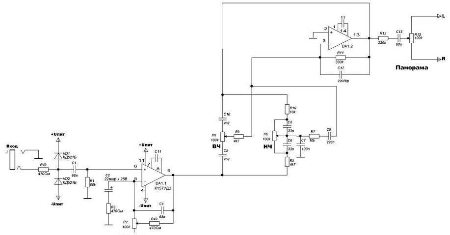
The four main input channels are identical and feature independently adjustable input sensitivity, tone, and sound panning. The fifth input is a linear channel. Despite its inexpensive and basic design, the Mini Audio Mixer "Impulse MM-04" performs satisfactorily. The Mini...
The problem with class-B amplifier design is that we start with an output stage in two halves, each with a non-linear response, which we then add together to try to give a linear response, i.e. so that a graph...

Ensure that the 12V (yellow) wire is connected to the right side of the D-connector (viewed from behind, with the connector holes facing away and the curved portion of the connector oriented upwards). The D-connector, commonly utilized in various electronic...
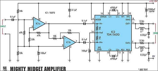
It is based on a Philips class-H audio amplifier integrated circuit and can deliver 36W RMS or 70W music power, all from a 13.8V supply. The new Mighty Midget Amplifier can produce approximately 36W RMS continuously into a 4-ohm...