
Mini AV Test Box Circuit

The Mini AV Test Box circuit is structured to facilitate various testing functionalities through its modular design. The 7805 voltage regulator serves as the heart of the power management system, ensuring that the microcontroller and other peripherals receive a consistent voltage level, which is critical for reliable operation. The input voltage is filtered by the 47µF capacitors to eliminate any high-frequency noise that could affect performance.
The VGA output section leverages the capabilities of the 16F84A microcontroller, which is programmed to generate the appropriate timing and signal levels necessary for VGA standards. This automatic generation of signals upon power-up simplifies the user experience, allowing for immediate functionality without additional setup.
The inclusion of a 6-pin header for programming and debugging purposes adds versatility to the design. This feature allows developers to upload new firmware or troubleshoot issues directly on the test box, enhancing its usability in development environments.
In the audio generation section, the 555 timer is configured in astable mode, producing a continuous square wave output that can be varied in frequency by adjusting the 100k trimpot. This feature enables the generation of a wide range of audio tones, making the Mini AV Test Box suitable for various testing applications, such as audio signal integrity checks and frequency response evaluations.
Overall, the Mini AV Test Box circuit is a compact and efficient solution for testing audio and video signals, making it an essential tool for electronics engineers and developers. Its straightforward design, combined with the flexibility of its components, allows for easy integration into various projects and applications.The Mini AV Test Box circuit is as simple and straight forward as I could design. It has three main sections that I split up in the schematic. The main devices used in the circuit are the 7805 +5v Regulator, 16F84A Microcontroller and 555 Timer. This is a very standard small scale power circuit that uses a 7805 to regulate the +9v input down to +5v. There are 47uF DC filtering capacitors on the input and output signals to/from the 7805. These help to keep the voltage level stable which the other digital devices in the circuit want to see. The first portion of functional circuitry is for creating the VGA output signals. The PIC does that automatically on power-up. A second set of connections are made to a 6-pin header which can be used for both programming and debugging the PIC if necessary.
This additional programming circuitry isn`t necessary if you don`t have to program your PIC `on-board`. This last portion of the schematic is where the Audio signal will be generated. The 555 timer is setup so that it will output tones from 70 Hz upto ear-piercing 14000 Hz, when the 100k trimpot is varied.
🔗 External reference
Related Circuits
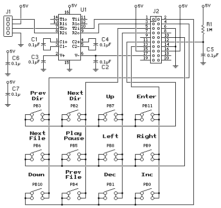
This process can be simplified by utilizing a display kit from PJRC, which includes the appropriate firmware installed on the display, a functioning pushbutton board, and the necessary cables. The PJRC display features a 4-pin connector compatible with the...
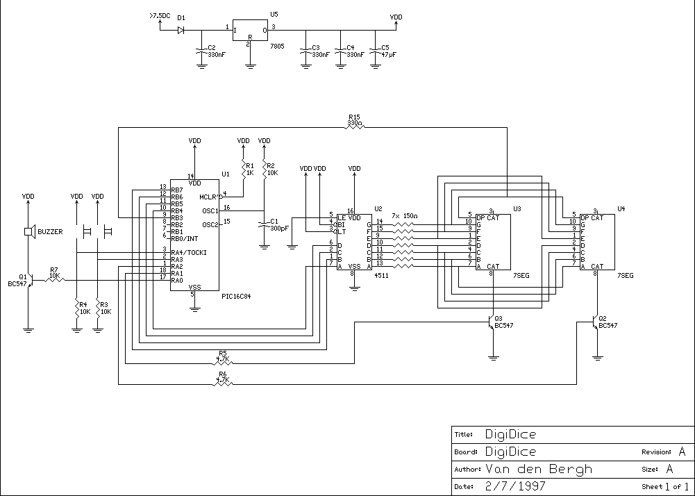
This is a digital dice circuit that uses the PIC16C84. The digital dice circuit utilizing the PIC16C84 microcontroller is designed to simulate the random rolling of a standard six-sided die. The circuit operates by generating a random number between 1...
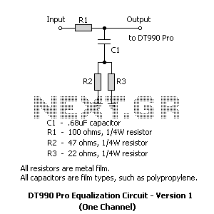
2 versions of the equalization circuit, the first having 6 dB less insertion loss than the other. However, some may not be able to find a 0.68 microfarad capacitor. The second version uses a more common 0.22 microfarad capacitor....
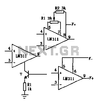
The LM111/211/311 power supply operates within a voltage range of 5V to 15V. It features bias current, offset current, and a differential input voltage range of 30V. The output is compatible with TTL, DTL, and MOS circuits, allowing it...
This is a convenient design for a transistor tester. The advantage of this circuit is that transistors can be tested without actually doing the circuit soldering. The tester uses two ICs: an NE 555 timer and a CMOS IC...
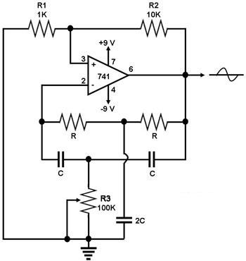
This circuit generates a sine wave using a single operational amplifier (741). The feedback loop of the op-amp includes a twin-T filter connected between its output and inverting input. Positive feedback for oscillation is provided by resistor R2. The...