
sine wave generator circuit

The sine wave generator circuit utilizing a single operational amplifier (741) is an effective design for generating sinusoidal waveforms. The operational amplifier is configured in a negative feedback arrangement with a twin-T notch filter, which is critical for achieving the desired oscillation. The twin-T filter is characterized by its unique configuration of resistors and capacitors, allowing it to create a notch in the frequency response at the specified frequency fn = 1/(2πRC).
In this configuration, one T-network consists of a resistor and two capacitors, while the second T-network is composed of two resistors and one capacitor. This arrangement ensures that at the notch frequency, the phase shift around the feedback loop is precisely zero degrees, which is a necessary condition for sustained oscillation. The resistor R2 is essential in providing the necessary positive feedback to enable the op-amp to oscillate.
The operational amplifier's output, which is a sine wave, can be adjusted for amplitude and frequency by modifying the values of the resistors and capacitors in the twin-T filter. This flexibility makes the circuit suitable for various applications, including signal generation, waveform shaping, and testing of audio equipment. The design is straightforward and cost-effective, leveraging the characteristics of passive components to achieve stable oscillations.
Overall, this sine wave generator circuit is a practical example of using operational amplifiers in waveform generation, demonstrating the fundamental principles of feedback and frequency response in electronic circuit design.This is a circuit for generating a sine wave from a single operational amplifier. The feedback loop of the op amp in this circuit (741) consists of a twin-T filter connected between its output and its inverting input. Positive feedback for oscillation is provided by R2. The twin-T filter (see Figure 2) is a passive notch filter composed of two T-n etworks, with maximum attenuation occurring at fn = 1/(2pRC). One of these T networks has one resistor and two capacitors, while the other has two resistors and one capacitor. At the notch frequency fn of the twin-T filter, the total phase shift around the loop gain of this op amp circuit is zero, which satisfies the requirement for oscillation.
This is why the circuit generates a sine wave with a frequency equal to fn = 1/(2pRC). 🔗 External reference
Related Circuits
This document provides a guide on understanding a simple computer system and its operation. It will examine the BASIC programming language and its statements, enabling communication with external circuitry. The document will also explore how to interface electronic circuits...
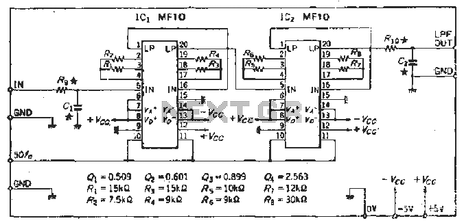
To create a Butterworth low-pass filter with a 12 dB/octave roll-off, four second-order (12 dB/oct) filter blocks are connected in series. This configuration is intended to achieve flat response characteristics across the frequency spectrum. The values for each stage...
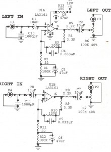
Preamplifiers are utilized to amplify low-level signals, such as those from microphones and tape heads, before they are sent to power amplifiers. Power amplifiers typically exhibit lower sensitivity. The frequency response can also be adjusted and optimized at the...
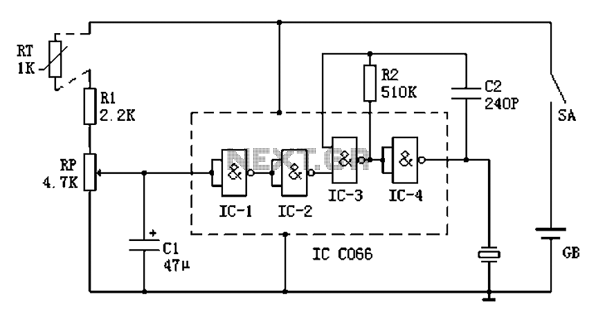
Boiling water on a kitchen gas stove can lead to issues such as spilling boiling water if the process is not monitored, which can extinguish the flame and cause gas leakage. A notification device can address this problem. The...
The function generator features two BNC outputs: one for the high speed [1 to 8 MHz] square signal (BNC1) and another for the DDS signal (BNC2). Offset and amplitude can be regulated by two potentiometers: offset in range of...
Using an old moving coil instrument, it is easy to create a simple voltmeter that indicates the status of a telephone line at a glance. The circuit's high input impedance allows it to be permanently connected to the line,...