
Mini UPS for DSL Modem and WiFi Routers

This circuit design is intended for applications requiring reliable power delivery to devices such as DSL or Wi-Fi routers. The core of the circuit consists of a power input section, which can accept a voltage range from 16V to 18V, typically sourced from a laptop charger. This input voltage is then regulated to provide the necessary power output for the connected devices, specifically 9V or 12V, depending on the requirements of the router or appliance.
For configurations involving a single 12V router, the circuit can be simplified by omitting the four diodes and the 9V output jack, which are primarily used for voltage regulation in more complex setups. The output from the circuit is connected to a DC pin, which serves as the interface to the router. This eliminates the need for an external adapter, streamlining the design and reducing component count.
When selecting a charger, it is crucial to ensure that the current rating aligns with the battery specifications. A charger with a current rating of 2A is likely to exceed the safe charging capacity of a 7AH battery, potentially leading to overheating or damage. Instead, a charger providing approximately 700mA is recommended for optimal charging speed without risking battery integrity. However, this lower current may result in longer charging times, which should be factored into the overall system design.
Overall, this circuit provides a practical solution for maintaining internet connectivity during power outages or in remote locations, offering a straightforward implementation that can be tailored to specific user needs. Proper attention to component selection and circuit design will ensure reliable performance and longevity of the connected devices.This is a rough, simple and NOT a sophisticated solution by me, but works! You can not only power DSL / WIFi routers for HOURS but also any other appliance that can work at 9V or 12V. Keep the internet alive, and use it on your laptop or cell phone, 24G—7! If you are only using a single router, just remove the respective part from circuit diagram. E. G, if you are using a 12V router, you don`t need those 4 diodes and 9V output jack. You need to attach a DC Pin to the outputs of the circuit. The same pin that is connected to your adapters, which go into your modem. Now, you don`t need that adapter. Just buy a same pin from the market. You can give input from a laptop charger of 16V to 18V. Keep in mind the current rating of charger too, as higher current ratings can damage the battery quite quickly. Even 2A current is too much for a battery of 7AH. It should be around 700mA, but that will also cause slow charging. 🔗 External reference
Related Circuits

This circuit operates as an astable multivibrator. With switch S9, an octave can be chosen. The tones are set by P1 to P8. Pressing S1 to S8 displays the corresponding note; pressing two buttons at the same time gives...
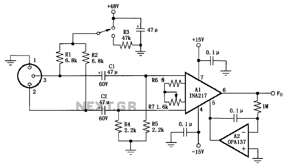
The circuit depicted in the figure consists of an INA217 professional miniature microphone preamplifier. A switch is included to select the use of phantom power. When the switch is connected to +48V, phantom power is enabled; if the switch...
A few months ago, I decided to build a compact, yet effective alarm. My demands were: simple construction, reliable operation, very small power consumption, and, most of all, small size. I started with CMOS logic gates, but was soon...
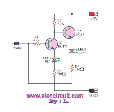
This logic probe circuit is designed for checking voltage levels in TTL circuits. It receives signals from the circuit being tested and indicates whether the logic level is high or low. When the input voltage at the probe tip...
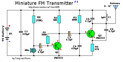
This is a mini FM transmitter designed by Tony van Roon, powered by two transistors. It is straightforward to assemble, and its transmissions can be received on any standard FM radio. The transmitter has an approximate range of 1/4...
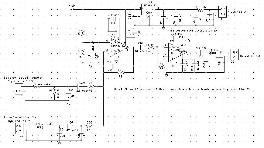
The audio mixer allows for easy comparison of various receivers by adjusting the gain controls without the need for switching. This setup simplifies A/B comparisons since all receivers are connected to the same antenna. Previously, different speakers were used...