
Mini Organ using timer 555

The described circuit functions as an astable multivibrator, which is a type of oscillator that continuously switches between its high and low states without requiring any external triggering. The circuit utilizes an NE555 timer integrated circuit (IC1) configured in an astable mode, generating square wave output signals.
The operation of the circuit begins with the selection of an octave using switch S9. This switch allows the user to choose between different frequency ranges, effectively altering the pitch of the generated tones. The tones themselves are determined by the variable resistors P1 through P8, which are 100kΩ spindle trimmers. Each of these trimmers adjusts the resistance in the timing circuit of the NE555, thereby changing the frequency of the output waveform, which corresponds to musical notes.
Pressing the buttons S1 to S8, which are normally open (NO) contacts, enables the user to select specific notes. When a button is pressed, it activates the corresponding tone, and if two buttons are pressed simultaneously, the circuit produces a combination tone. This feature allows for chord generation, enhancing the musical capabilities of the circuit.
The output from the NE555 timer is taken from the 'out' point, which can be connected to an amplifier. This amplifier will boost the signal to a level suitable for driving speakers or other audio output devices, allowing the generated tones to be heard clearly.
The circuit components include resistors and capacitors that define the timing characteristics of the NE555. For instance, R1 is a 10kΩ resistor, while capacitors C1, C2, C3, and C4 are used to set the timing intervals for the oscillation. C1 and C4 are 100nF capacitors, C2 is a 150nF capacitor, and C3 is a 10nF capacitor. The selection of these component values determines the frequency range and stability of the oscillation, which is critical for producing musical tones accurately.
In summary, this astable multivibrator circuit with octave selection and tone generation capability provides a versatile platform for sound synthesis, suitable for various electronic music applications.This circuit operates as a astabiele multivibrator. With switch S9 can 'octave' chosen. The tones are set by P1 to P8. Pressing S1 to S8 displays the corresponding note, pressing two buttons at the same time gives it a tone. At the point 'out' can be connected to an amplifier show display. Parts List R1 = 10k? P1 .. P8 = 100k? (spindle trimmers) C1 = 100nF C2 = 150nF C3 = 10nF C4 = 100nF IC1 = NE555 S1 .. S8 = NO contact S9 = way switch 🔗 External reference
Related Circuits
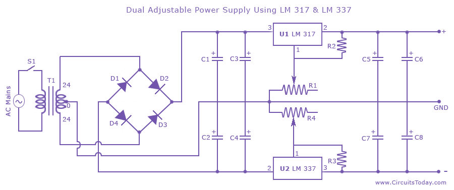
Dual adjustable power supply circuit with a diagram using IC LM317 and LM337. This variable power supply circuit has a range of 1.2 volts to 30 volts. The dual adjustable power supply circuit utilizes the LM317 and LM337 voltage regulators...
Here is a circuit for using the printer port of a PC, for control application using software and some interface hardware. The interface circuit along with the given software can be used with the printer port of any PC...

This amplifier was designed to be self-contained in a small loudspeaker box. It can be fed by Walkman, Mini-Disc, iPod, CD players, computers, and similar devices fitted with line or headphone output. Of course, in most cases, you will...
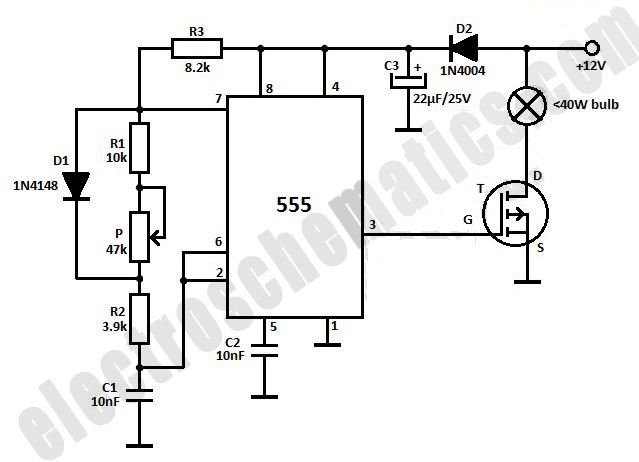
This light dimmer is designed to adjust the brightness of 12V light bulbs utilizing the widely recognized 555 timer, which is configured as an astable multivibrator. The pulses generated by the timer control the power delivered to the light...
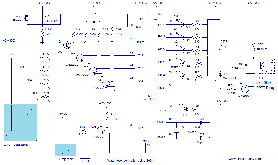
A water level controller based on the 8051 microcontroller is presented in this article. While numerous water level controller projects have been published on this website, this is the first one utilizing a microcontroller. The water level controller monitors...
The circuit is composed of a 555 oscillator and an amplifier driver stage. It includes the 555 timer along with resistors R1, R2, RP1, capacitor C1, and other components forming a multi-harmonic oscillator. The frequency can be adjusted using...