
Mini Voice Operated RelayCircuit

The voice-operated relay circuit typically consists of a microphone, an amplifier, a comparator, and a relay module. The microphone captures sound waves and converts them into electrical signals. These signals are then amplified to ensure they are strong enough for further processing.
The amplified signal is fed into a comparator circuit, which compares the input signal against a predefined threshold level. When the sound exceeds this threshold, the comparator output changes state, signaling the relay to activate. This activation allows the relay to close its contacts, thereby connecting the output to the power source or load.
The relay is a crucial component in this circuit, as it provides electrical isolation between the low-power sound detection circuit and the high-power load. It ensures that the circuit can safely control devices that require higher voltages or currents without risking damage to the sound detection components.
Additionally, the circuit may include a delay mechanism to prevent false triggering from transient sounds or noise. This can be implemented using a simple RC (resistor-capacitor) timing circuit or a more sophisticated microcontroller-based approach, depending on the desired complexity and reliability of the system.
Overall, the voice-operated relay circuit is an effective solution for applications requiring sound-based control, such as automated lighting systems, remote switching, or interactive installations.This is the circuit diagram of a voice operated relay. It similar with sound activation switch circuit which will turn on and turn off (connect and disconnect) the switch depending on the sound input. The output switch of this circuit is act by a relay. 🔗 External reference
Related Circuits

Using a Thomson TEA2025, this stereo amplifier delivers 1 W per channel into a 4-ohm load with a 9-V supply. The input sensitivity is 25 mV peak-to-peak for full output. It is important to ensure that pins 4, 5,...
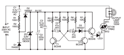
Components such as resistors R1 and R2, capacitors C1, C2, and C3, diodes D1 and D2, and a zener diode ZD1 are utilized to create a stable 5V DC supply voltage that delivers the necessary current to operate the...
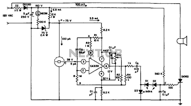
An ionization chamber in conjunction with a high-impedance CA3130 operational amplifier is utilized to detect the presence of smoke. When smoke is detected, the CA3130 ceases oscillation, which in turn triggers the S106D silicon-controlled rectifier (SCR) to sound an...
R1 2.2K 1/4W Resistor, R2 27K 1/4W Resistor, R3, R4 2.2K 1/2W Trimmers (Cermet or Carbon), R5 100R 1/4W Resistor, R6 1K 1/4W Resistor, R7, R8 330R 1/4W Resistors, C1 22 µF 25V Electrolytic Capacitor, C2 47pF 63V Polystyrene...
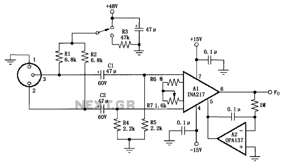
The circuit depicted in the figure consists of an INA217 professional miniature microphone preamplifier. A switch is included to select the use of phantom power. When the switch is connected to +48V, phantom power is enabled; if the switch...
This low-power NTSC video and sound transmitter is suitable for amateur radio, video handheld transceivers, remote control applications, and surveillance purposes. It features a crystal oscillator-multiplier and a power amplifier. Video modulation is achieved through a three-transistor series modulator....