
220v ac operated christmas light star

The circuit design employs a combination of discrete components to achieve a reliable 5V DC supply, which is crucial for the operation of the multivibrator and the triggering of the triac. The inclusion of diodes D1 and D2 ensures proper rectification and protection against reverse polarity, while the zener diode ZD1 stabilizes the voltage to maintain a consistent output under varying load conditions.
The multivibrator configuration, consisting of two BC548 transistors, operates in an astable mode. The resistors R3 through R7 and capacitors C4 and C5 dictate the timing characteristics, allowing for precise control over the output frequency. This frequency modulation is essential for the desired operation of the connected load, in this case, a lamp.
Transistor T3 serves as a switch that amplifies the output signal from the multivibrator to drive the triac BT136. The LED1 acts as an indicator, providing visual feedback when the triac is activated. The triac, once triggered, allows current to flow through the connected lamp, thus illuminating it during the positive half cycles of the output signal.
The overall design is cost-effective, with an estimated total expense of Rs 75, making it an economical solution for applications requiring a controlled lighting mechanism. The schematic effectively integrates the components to ensure reliable performance and operational efficiency.Components like resistors R1 and R2, capacitors C1, C2, and C3, diodes D1 and D2, and zener ZD1 are used to develop a fairly steady 5V DC supply voltage that provides the required current to operate the multivibrator circuit and trigger triac BT136 via LED1. The multivibrator circuit is constructed using two BC548 transistors (T1 and T2) and some passive components. The frequency of the multivibrator circuit is controlled by capacitors C4 and C5 and resistors R3 through R7. The output of the multivibrator circuit is connected to transistor T3, which, in turn, drives the triac via LED1.
During positive half cycles of the multivibrator`s output, transistor T3 energises triac BT136 and the lamp glows. This circuit is estimated to cost Rs 75. 🔗 External reference
Related Circuits
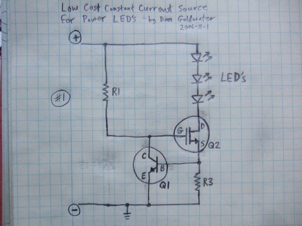
Here is a simple and inexpensive ($1) LED driver circuit. The circuit functions as a constant current source, ensuring that the LED maintains consistent brightness. The LED driver circuit is designed to provide a stable current to the LED, which...

Figure 2-39 illustrates a typical application circuit for the JS88 manifold, which includes an oscillation resistor (R) that allows for fine-tuning of the water flicker frequency. When switch (S) is closed, components L1 to L5 sequentially output low signals...

This circuit diagram illustrates a voice-operated relay, which functions similarly to a sound-activated switch circuit. It activates and deactivates the switch based on sound input. The output switch of this circuit is controlled by a relay. The release time...

Toyota MR2 Exterior Lights Wiring Diagram Manual PDF Download. The Toyota MR2 Exterior Lights Wiring Diagram Manual provides a comprehensive guide for understanding the wiring configurations associated with the exterior lighting system of the Toyota MR2 model. This manual is...
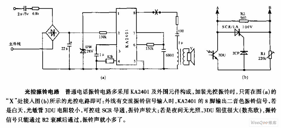
The average telephone ring circuit consists of the KA2401 integrated circuit and its associated peripheral components. To integrate a light-operated ring circuit, connect the designated part X in the provided diagram (picture a) to the light-operated circuit shown in...

The chart illustrates a Christmas lights circuit that employs a simple and cost-effective CD4069 CMOS hex inverter to control four separate circuits, each consisting of 50 light-emitting diodes (LEDs), totaling 200 LEDs. The circuit is powered directly by a...