
misc

The circuit design for controlling a servo motor using a 555 timer is straightforward yet effective. The 555 timer operates in astable mode to generate a pulse-width modulation (PWM) signal, which is crucial for servo control. The duty cycle of the PWM signal determines the angle to which the servo motor will turn.
In this circuit, the potentiometer serves as an adjustable input that modifies the width of the PWM signal. As the potentiometer is turned, it alters the resistance in the circuit, which in turn changes the timing of the 555 timer. This results in varying pulse widths sent to the servo motor, allowing it to rotate to the desired angle within its range of motion.
The key components of the circuit include:
1. **555 Timer IC**: This integrated circuit is the heart of the circuit, generating the PWM signal.
2. **Potentiometer**: A variable resistor that allows the user to set the desired angle by adjusting its position.
3. **Servo Motor**: The actuator that receives the PWM signal and rotates its shaft to the specified angle.
4. **Resistors and Capacitors**: These components are used to set the timing parameters of the 555 timer, determining the frequency and duty cycle of the output signal.
The circuit can be powered by a standard DC power supply compatible with the servo motor's voltage requirements. Proper connections must be made to ensure that the ground of the power supply, the 555 timer, and the servo motor are all common to avoid erratic behavior.
This simple yet effective design demonstrates the versatility of the 555 timer in controlling servo motors, making it an excellent choice for applications in robotics and automation projects where precise positioning is required.The servo motor have many utilizes in everything from robotics to puppetry to photography and beyond. These tiny motors can position their output shaft to any position on command and hold that position. Most servos possess a range of motion to about 210 degrees and thankfully are quite easy to handle with a basic circuit like the one presented rig
ht here. Working with just a 555 timer as well as a couple of support parts, this circuit can handle a servo via it is full rotation primarily based on the position of a potentiometer. 🔗 External reference
Related Circuits

A diode (IN4148) is utilized as a temperature sensor. IC2 is an A/D converter with BCD output. A reference voltage set by R7 is applied to the positive input of IC2. As the temperature rises, the voltage across the...
If an application utilizes a MOSFET to switch a load, it is straightforward to incorporate short-circuit or overload protection. This can be achieved by leveraging the internal resistance RDS(ON), which generates a voltage drop proportional to the current flowing...
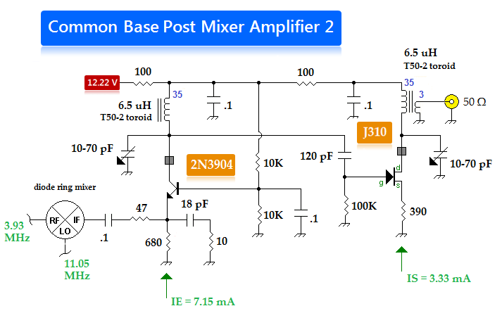
The local oscillator (LO) system from the project titled "A Monoband SSB/CW Transceiver" in Chapter 6 of EMRFD. The low output (approximately -20 dBm) from a diode ring mixing a variable frequency oscillator (VFO) and crystal oscillator is triple-tuned...
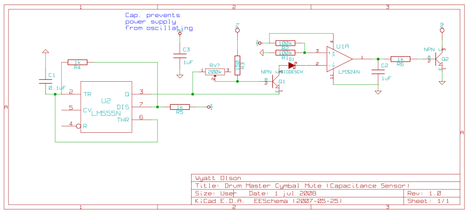
This page contains various small circuits created over time. Some circuits are trivial, while others are more complex, but all are intended to be useful for a variety of projects. Most include both the schematics and the source (KiCad)...