
Bass And Treble Controller Circuit Based On The Classic Baxandall Tone Control Circuitry

The Bass and Treble Controller Circuit is designed to adjust the low and high-frequency response of audio signals, allowing for enhanced sound quality and tailored audio experiences. The circuit typically employs operational amplifiers (op-amps) configured in a feedback arrangement to achieve the desired tone control characteristics.
The classic Baxandall configuration utilizes two primary stages: one for bass control and another for treble control, each incorporating variable resistors (potentiometers) to adjust the gain of the respective frequency bands. The circuit generally includes capacitors to filter specific frequency ranges, ensuring that the adjustments made do not adversely affect the overall audio signal integrity.
In a typical implementation, the bass control section may consist of a low-pass filter, which allows frequencies below a certain threshold to pass while attenuating higher frequencies. Conversely, the treble control section functions as a high-pass filter, allowing frequencies above a designated point to be amplified while reducing lower frequencies.
The output of the circuit is designed to be connected to a power amplifier or directly to a speaker system, enabling users to modify their audio output dynamically. The use of high-quality components, such as low-tolerance resistors and capacitors, is recommended to maintain fidelity and minimize noise in the audio signal.
This circuit is particularly valuable in audio applications where user preference for low and high frequencies can significantly impact the listening experience, making it a staple in both consumer electronics and professional audio equipment.The following circuit shows about Bass And Treble Controller Circuit. This circuit built based on the classic Baxandall tone control circuitry .. 🔗 External reference
Related Circuits
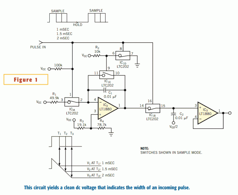
The circuit in Figure 1 converts pulse information to a clean dc voltage by the end of a single incoming pulse. In another technique, an RC filter can convert a PWM signal to an averaged dc voltage, but this...
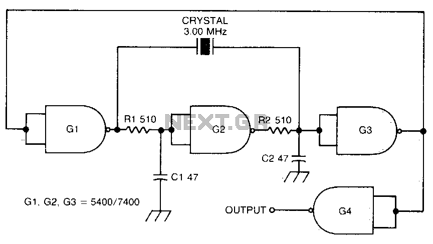
This circuit oscillates without the crystal. When the crystal is included in the circuit, the frequency will match that of the crystal. The circuit exhibits good starting characteristics even with low-quality crystals. This circuit design features a basic oscillator configuration...
12V Battery Charge Nominal Discharge (Low) Indicator Circuit. This circuit monitors car battery voltage and provides an indication of nominal levels. The 12V Battery Charge Nominal Discharge Indicator Circuit is designed to monitor the voltage levels of a car battery...
This is a preselector circuit designed for shortwave (SW) receivers, specifically a do-it-yourself (DIY) high-frequency preselector. The circuit employs a modern low-capacitance MOSFET with two gates, which generates a negative inverse reaction through an uncoupled source resistor. When applied...
This document serves as a compilation of design notes, providing practical details as construction progresses, along with some photographs that will be included in due course. Currently, it functions as a progress report, blending immediate plans with actual construction,...
Switching regulator subsystems intended for use as DC to DC converters. 3V to 40 Volt DC Converter circuit. The use of switching regulators is becoming more pronounced than that of linear regulators because the size reductions in new equipment...