
SCR Mini Power Inverter

The Mini Power Inverter is designed to convert a low DC voltage (12V) into a high AC voltage (300V) using a silicon-controlled rectifier (SCR) as the primary switching element. The inverter's operation begins with the input voltage being fed into an oscillator circuit, which generates a square wave signal at a frequency of 400Hz. This frequency is suitable for various applications that require a stable AC output.
The SCR is essential in this circuit as it allows for controlled switching of the output voltage. When the oscillator generates a signal, the SCR is triggered to conduct, allowing current to flow through the load connected to the inverter. The inverter's design typically includes additional components such as capacitors and inductors to filter and stabilize the output waveform, ensuring a cleaner and more usable AC signal.
In practical applications, this Mini Power Inverter can be used in various fields, including renewable energy systems, portable power supplies, and small appliances that require an AC input. Its compact design and efficient operation make it a valuable component for converting low-voltage DC power into high-voltage AC power, suitable for powering devices that operate on standard AC voltage levels. Proper thermal management and circuit protection mechanisms should be integrated to enhance reliability and prevent damage during operation.This be Mini Power Inverter , by use SCR be main part electronics , perform Oscillator Generator 400Hz give Output 300V by use Voltage Input 12V Current.. 🔗 External reference
Related Circuits
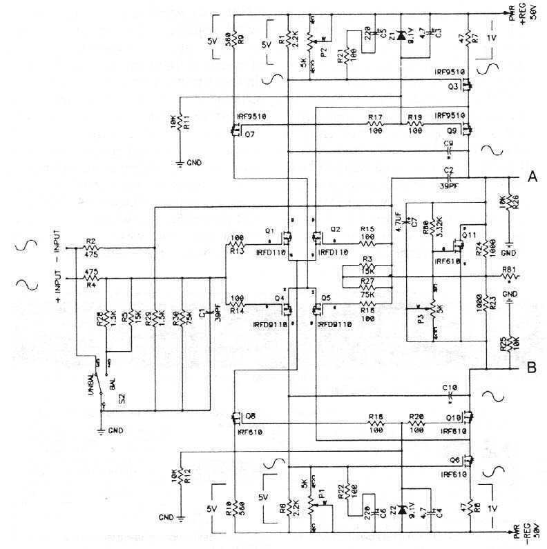
The MOSFETS we are dealing with are three terminal devices which are used to control electron flow in a circuit. Two of the pins (the source and drain) pass the current, and the third pin (the gate) is used...
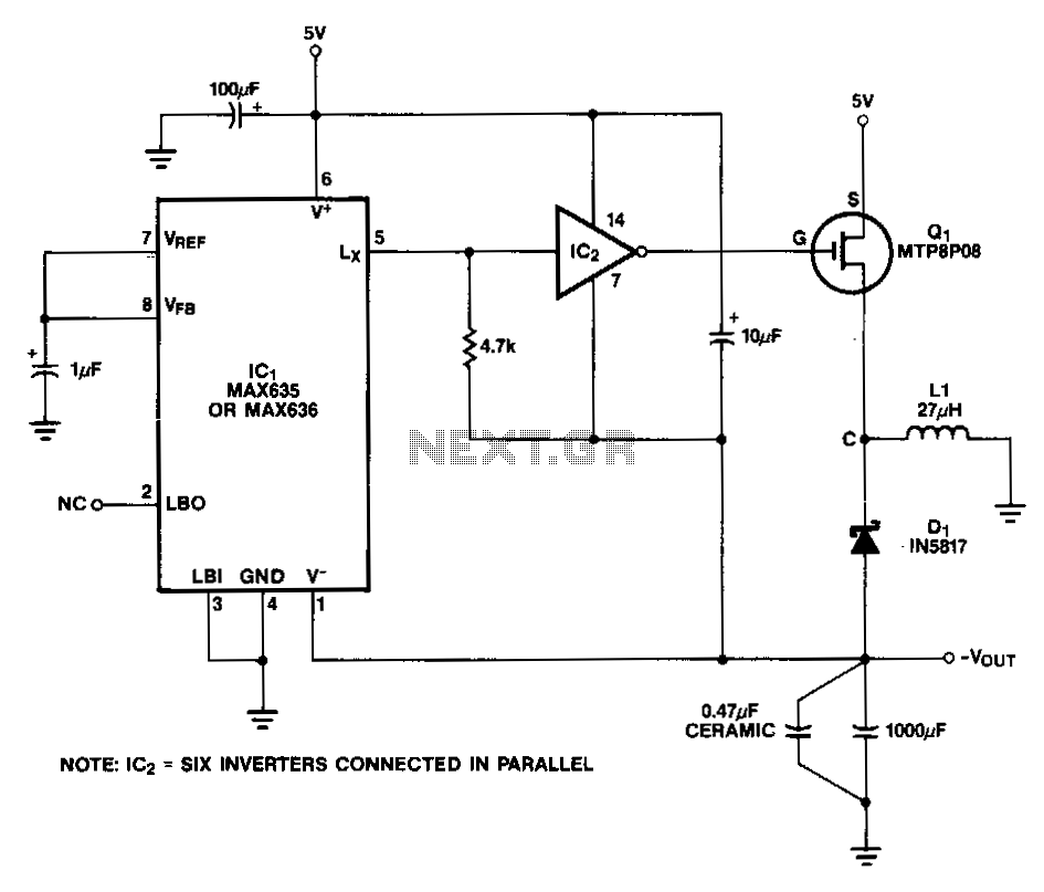
In this circuit, a CMOS inverter, such as the CD4069, is utilized to convert the open-drain Lx output into a signal that is appropriate for driving the gate of an external P-channel MOSFET. The MTP8P03 has a gate threshold...
One 1381 part (CMOS voltage-controlled trigger available at different limits) should be selected to match the voltage across the motor (2V in this case). The other terminal of the motor is connected to a 3300µF capacitor, which is in...
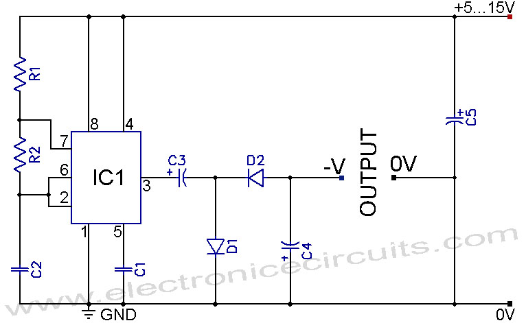
A 555 negative voltage power supply circuit can be created using a charge-pump configuration that incorporates a 555 timer, diodes, and additional components. The 555 timer is a versatile integrated circuit commonly used in various applications, including oscillators, timers, and...
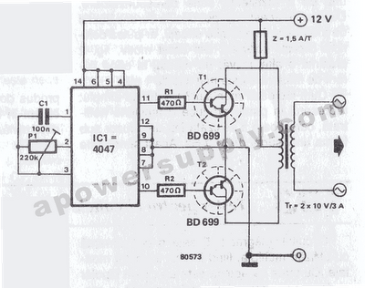
The inverter circuit features the CMOS 4047 as its primary component, converting a 12V DC voltage to a 220V AC voltage. The 4047 operates as an astable multivibrator. A symmetrical rectangular signal is generated at pins 10 and 11,...
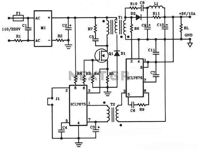
The following diagram illustrates a 50W offline switching power supply circuit design. This circuit is powered by a MOSFET, specifically the BUZ80A/IXTP4N8 for a 220V AC voltage input and the GE IRF823 for a 110V AC voltage input. The...