
Model rocket launch controller

The circuit utilizes eight light-emitting diodes (LEDs) arranged to indicate the active pad selection in a user interface. These LEDs are connected to a decade counter, typically a CD4017 or similar, which serves to sequentially activate each LED in response to clock pulses. The operation is such that only one LED is illuminated at any given time, minimizing the current draw from the power source and ensuring efficient battery usage.
The clock signal necessary for the decade counter is produced by a 555 timer configured in astable mode. This configuration allows the timer to generate a continuous square wave output, which serves as the clock pulse for the counter. The frequency of the clock can be adjusted by varying the resistor and capacitor values in the 555 timer circuit, allowing for control over the speed at which the LEDs are cycled.
The control interface for this circuit includes six input lines that connect to a main controller. These lines are responsible for receiving signals that dictate which pad is selected. Depending on the logic levels present on these lines, the decade counter will be triggered to advance its count, thus lighting the corresponding LED. The simplicity of the circuit design facilitates easy integration into larger systems while maintaining clarity in operation.
Overall, this circuit exemplifies a straightforward yet effective method for visual pad selection indication using discrete components, ensuring low power consumption and ease of implementation.Eight LED`s are used to indicate the pad currently selected. These LED`s are connected to a decade counter, which sequences the LED`s when it receives a clock pulse.Only one LED can be lit at a time from the decade counter, so although this circuit contains many LED`s only a small drain us placed on the battery. The clock pulse for the decade counter is generated by a 555 timer. The circuit diagarm for the pad unit is very simple. Six input lines receive the signals from the main controller. I don`t think I need to explain this part of the circuit in detail, although I will mention a few things. Firstly make sure that the re 🔗 External reference
Related Circuits
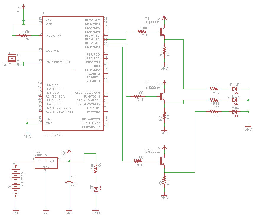
A very popular type of LED that has finally emerged is the tri-color, RGB LED. The RGB stands for red, green, and blue, as the LED is capable of displaying various colors through the combination of these three primary...

Utilize a PIC Microcontroller to Control a Hobby Servo. This guide outlines the process of incorporating hobby servos, typically found in remote-controlled airplanes, cars, and similar devices. To implement the control of a hobby servo using a PIC microcontroller, the...
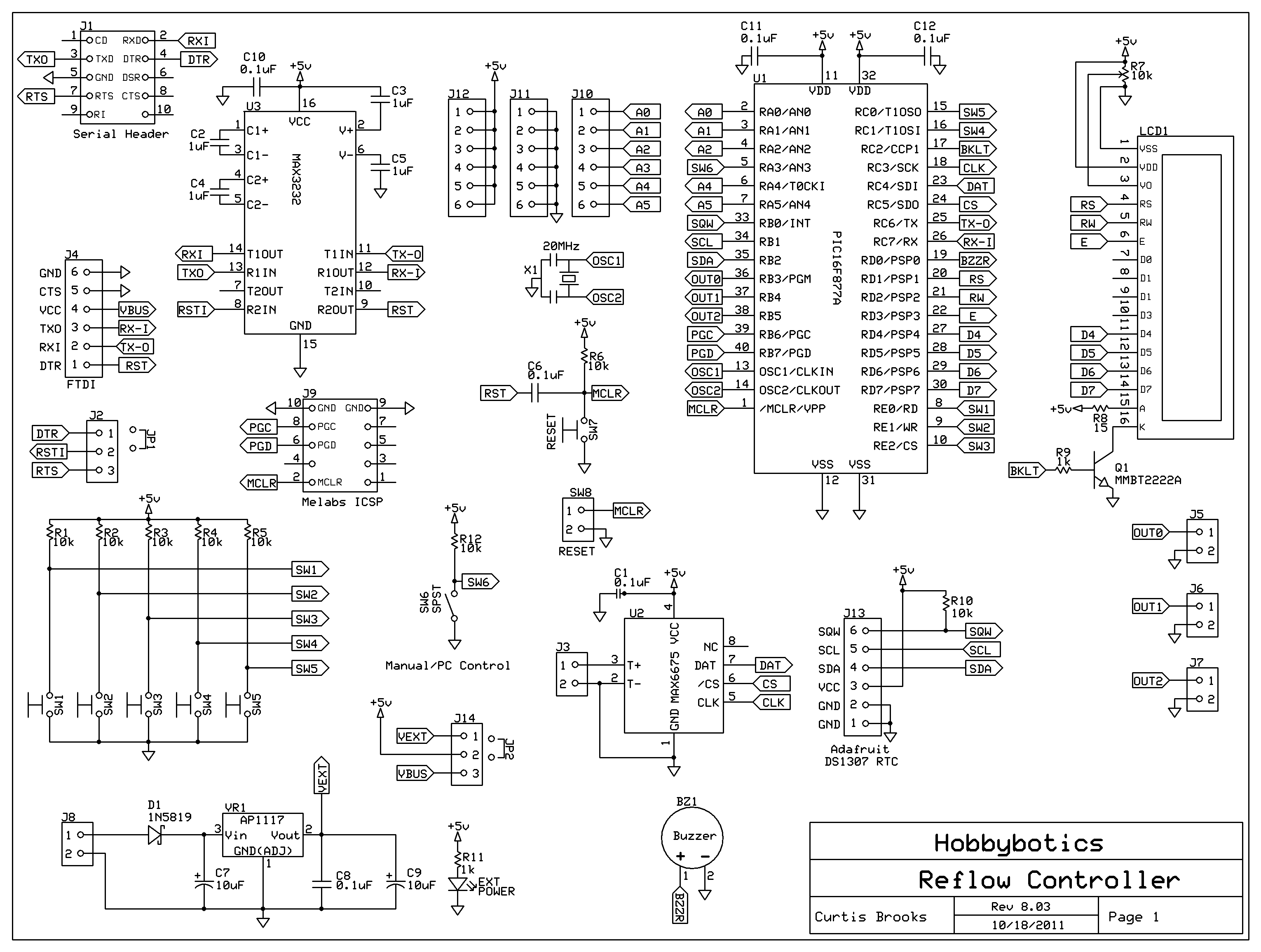
Introduction to the Reflow Process and PID Controller Circuit Documentation. This document discusses the benefits of using Surface Mount Devices (SMD) in circuit design, highlighting advantages such as reduced size and cost compared to traditional through-hole components. The reflow soldering...
The objective of the project is to develop a robot capable of following a black line on a white sheet of paper and navigating through a maze constructed from these materials. The maze specifications include black lines with a...
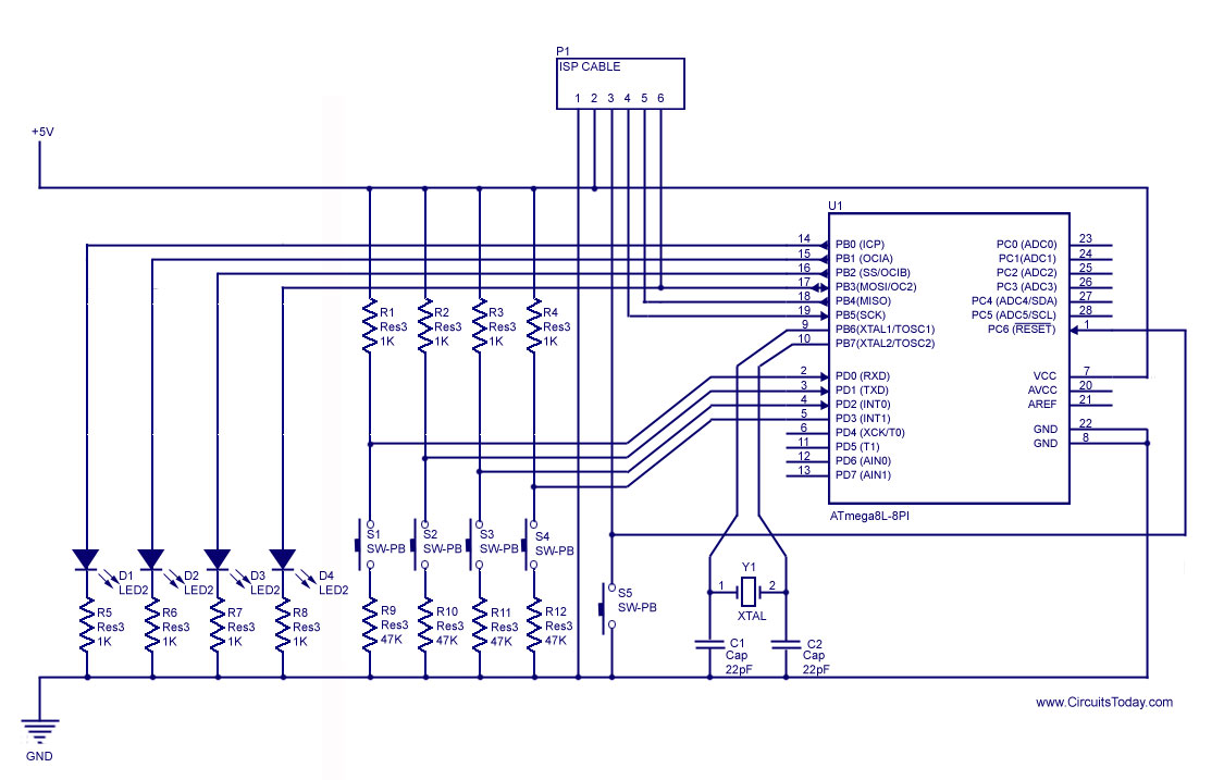
How to handle digital input/output (I/O) in AVR microcontrollers is explained using basic programs and circuits to illuminate an LED, generate a stepper motor sequence, read a push-button switch, and implement key debouncing. The handling of digital I/O in AVR...
This project provides a simple temperature-controlled fan. If the difference between the actual temperature and the user-defined temperature is significant, the fan will operate. The temperature-controlled fan circuit utilizes a temperature sensor, a microcontroller, and a fan motor to regulate...