
Model Theatre Lighting Dimmer

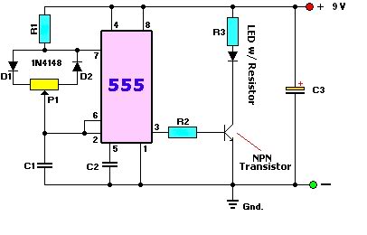
The circuit design incorporates a 555 timer, which is a versatile integrated circuit commonly used in timing applications. In this setup, it operates in monostable mode, triggered by the zero-crossing detector. The zero-crossing detector, implemented with transistors Q1 to Q3, ensures that the timing begins precisely at the moment when the AC waveform crosses zero volts, allowing for synchronized control of the lighting.
The timing period of the 555 timer is crucial for dimming control. The capacitor C2 charges and discharges based on the resistance values of R6, VR1, and VR2. As VR1 is adjusted, the resistance changes, altering the timing interval. This adjustment directly influences how long the Triac remains on during each half cycle of the AC waveform, thus controlling the brightness of the connected lights.
Transistor Q5 plays a vital role in driving the Triac. By inverting the output signal from the 555 timer, it ensures that the Triac is triggered appropriately. The 100Ω resistor limits the current flowing into the gate of the Triac, protecting the components and ensuring reliable operation.
The overall functionality of the dimmer circuit allows for smooth transitions in lighting levels, which is particularly important in theatrical settings, where lighting can significantly impact the audience's experience. The combination of the adjustable potentiometer VR1 and the trimpot VR2 provides a flexible range of control, enabling the user to achieve desired lighting effects with precision. This circuit exemplifies a practical application of fundamental electronic components in creating an effective dimming solution for theatre lighting systems.This circuit is the basis for the dimmers in a model theatre lighting system which uses touch globes as the light source. The circuit is based around a 555 timer, driving a Triac. All dimmers share the one power supply and zero-crossing detector. As it will only work if there is a common AC/DC return path, it has a simple DC supply circuit consist
ing of one 1N4004 diode and one 4700 µF capacitor. Transistors Q1 to Q3 comprise a zero-crossing detector whose output is inverted into a negative-going pulse by Q4. This pulse is fed to the trigger input (pin 2) of the 555 IC which then starts its timing period at the beginning of each mains half cycle.
The length of this period is set by capacitor C2 and the combination of resistors R6 with pots VR1 and VR2. The output of IC1 at pin 3 is then fed to transistor Q5 which inverts this signal to trigger the Triac via a 100# resistor.
When the timing period is short, the Triac is turned on early in half cycle and lights are bright. Conversely, when the timing period is longer, the lights are dim or turned off. The main dimmer control is potentiometer VR1. Trimpot VR1 is used to set the range of VR1. With VR1 set fully clockwise (ie, maximum resistance) trimpot VR2 is adjusted until the lights are just turned off. The lights should then be able to be faded over the full range by the control potentiometer. 🔗 External reference
Related Circuits
A user is new to the forum and has limited experience in DIY electronics. The current project involves creating a battery-powered LED dimmer circuit. The objective of the project is to design a battery-operated LED dimmer circuit that allows for...
Note: Do not build or use this if you do not have any knowledge in electrical or electronics. This project is not safe for beginners, and the voltage involved is dangerous and can cause electrocution. Do not exceed the...
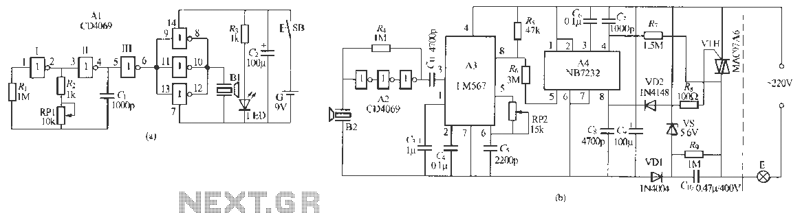
Remote control dimmer lights consist of two parts: an ultrasonic transmitter and an ultrasonic remote control dimmer receiver. The ultrasonic wave transmitter circuit is detailed in A 229 (a). It includes components such as R, R., RP1, and C,...
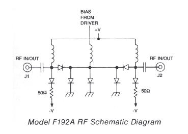
High-speed frequency range of 0.2 to 18 GHz with 80 dB isolation. Features non-reflective performance, low Voltage Standing Wave Ratio (VSWR), and minimal insertion loss. Compact and lightweight design. This electronic component is designed to operate efficiently across a broad...

This application note discusses the use of SEPIC power modules to supply the necessary power for driving high-brightness LED arrays. These arrays serve as display backlights and necessitate a wide dimming range. The SEPIC configuration offers an efficient and...
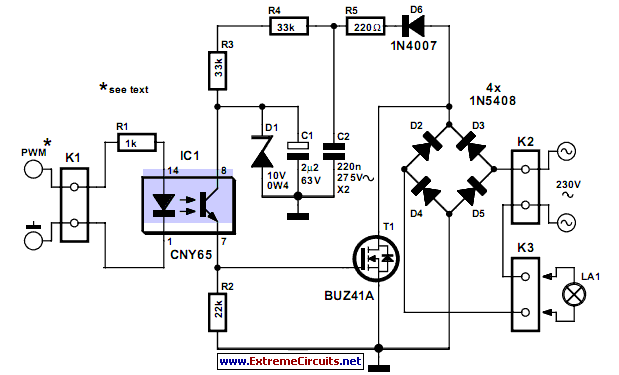
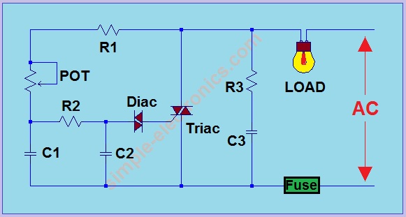
This circuit demonstrates that dimmers designed for mains voltage do not always require a triac. In this case, a MOSFET (BUZ41A, 500 V/4.5A) is utilized in a diode bridge configuration. The described circuit employs a MOSFET as the primary switching...