
Display Backlighting Using High-Brightness LEDs and SEPIC Power Modules

The SEPIC (Single-Ended Primary-Inductor Converter) topology is particularly advantageous for applications requiring a regulated output voltage that may be higher or lower than the input voltage. In the context of driving high-brightness LED arrays, the SEPIC power module can efficiently convert varying input voltages while maintaining a consistent output suitable for LED operation. This is crucial for display backlighting, where brightness control is essential for optimal visual performance.
In typical applications, the SEPIC converter utilizes two inductors, a switch (usually a MOSFET), a diode, and a capacitor to regulate the output voltage. The operation begins with the switch being turned on, allowing current to flow through one inductor, storing energy in its magnetic field. When the switch is turned off, the energy stored in the inductor is transferred to the output capacitor and the load, providing power to the LED array. This sequence allows for the output voltage to be adjusted based on the duty cycle of the switch, facilitating a wide dimming range.
Furthermore, the SEPIC architecture supports the use of feedback mechanisms to maintain voltage regulation. A feedback loop can be implemented using a voltage divider connected to the output, feeding back a portion of the output voltage to the control circuit. This ensures that any fluctuations in load or input voltage do not adversely affect the performance of the LED array.
The flexibility of the SEPIC design allows for easy integration into various LED applications, accommodating different sizes and configurations of LED arrays. Additionally, the efficiency of the SEPIC converter minimizes heat generation, which is vital for maintaining the longevity and performance of high-brightness LEDs.
In conclusion, the SEPIC power module represents a robust solution for powering high-brightness LED arrays, offering efficiency, flexibility, and the ability to achieve a wide range of brightness levels necessary for effective display backlighting.This application note discussed the use of SEPIC power modules to provide the power needed to drive high-brighness LED arrays. The arrays are used as display backlights and require a wide dimming range. The SEPIC approach provides an efficient and flexible approach for the backlights.. 🔗 External reference
Related Circuits
There is no substitute for sheer power—low-efficiency speakers, outdoor sound systems, or perhaps the full dynamic range of a high-power amplifier. Whatever the requirement, this super power module should meet the needs. The amplifier can be divided into three...
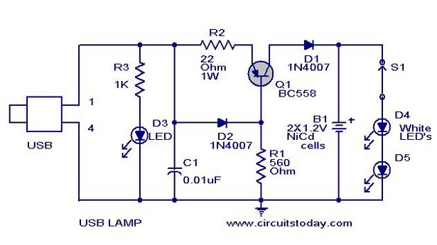
A simple USB LED lamp circuit utilizing a 5-volt power supply sourced from a USB port, designed to illuminate a desktop or laptop computer during power outages. The USB LED lamp circuit operates by converting the 5-volt DC power provided...

This circuit is designed for an LM1893 power line modem, which facilitates information transfer between remote locations using the power mains. The LM1893 serves as a power line interface for half-duplex (bi-directional) communication of serial bit streams employing various...
A 6-watt audio amplifier circuit utilizing the TDA2613 is presented here. The TDA2613 is an integrated Hi-Fi audio amplifier IC produced by Philips Semiconductors. The IC is designed for high-quality audio amplification. The circuit features the TDA2613 IC, which is...
This module utilizes the highly integrated MAX2830 RF transceiver, providing a complete RF front-end solution that complies with the WLAN IEEE 802.11b/g standard. The MAX2830 RF transceiver is designed for wireless communication applications, specifically targeting WLAN systems. It integrates various...
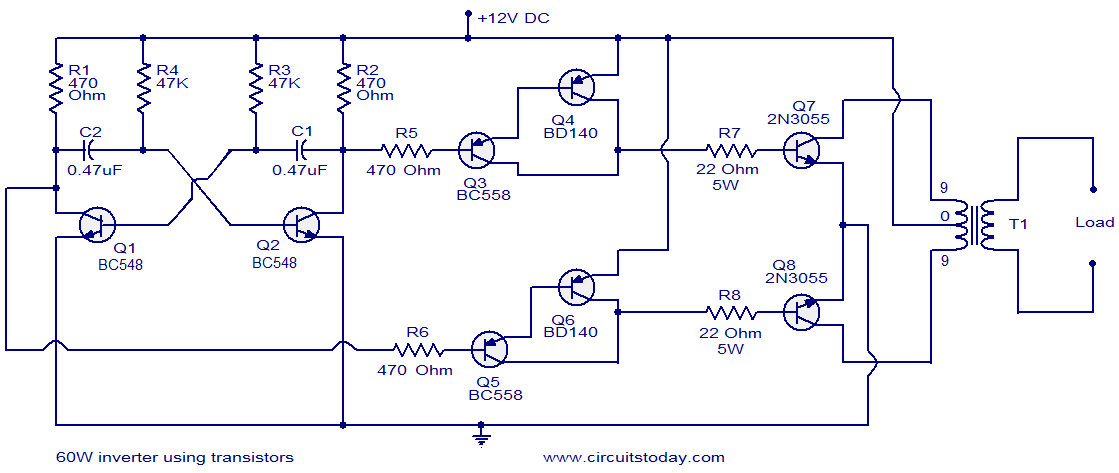
This circuit diagram illustrates a fully transistorized inverter capable of driving loads of up to 60W. Transistors Q1 and Q2 create a 50Hz astable multivibrator. The output from the collector of Q2 connects to the input of a Darlington...