
Modern FM Converter

The proposed design features a modern receiving converter tailored for pre-war FM radio sets, which traditionally operate within the 42 to 50 MHz frequency range. The converter utilizes a MOSFET transistor for its amplification and a TTL packaged oscillator for frequency generation, allowing compatibility with contemporary FM stations, such as the chosen frequency of 101.1 MHz.
The circuit begins with the input stage, where the audio signal from the antenna is fed into a bandpass filter, designed to isolate the desired frequency range while attenuating unwanted signals. The filtered signal is then amplified by the MOSFET transistor, which provides the necessary gain to drive the subsequent stages of the circuit.
Following the amplification, the TTL oscillator generates a local oscillator signal at a frequency that, when mixed with the incoming FM signal, produces an intermediate frequency (IF) suitable for further processing. The mixing process can be achieved using a diode mixer or an active mixer configuration, which combines the amplified RF signal with the local oscillator signal to create the IF output.
The IF signal is then passed through another bandpass filter to remove any unwanted harmonics or spurious signals generated during the mixing process. This filtered IF signal is subsequently demodulated to recover the original audio signal. Demodulation can be accomplished using various techniques, such as a phase-locked loop (PLL) or a simple envelope detector, depending on the desired fidelity and complexity of the design.
Finally, the demodulated audio signal is amplified again, if necessary, to drive the audio output stage, which can be connected to the pre-war FM radio's audio input. This entire system allows users to enjoy modern FM broadcasting while utilizing their vintage radio equipment, effectively bridging the gap between historical technology and contemporary audio enjoyment.Here is my design for a modern receiving converter for pre-war FM sets. Accordingly, this article presents a design for listening to present day FM stations on a prewar FM set based on a MOSFET transistor and a TTL (transistor-transistor logic) packaged oscillator. Someone else might have done it with vacuum tubes, but this design suits me fine. It is all a matter of taste. My FM radio station of choice is at 101.1 MHz. I specialize in FM only radios, so listening to this station is no problem on most of my sets. But prior to WWII, the FM radio band covered 42 to 50 MHz. These prewar FM radios are nearly useless. Turn one on 🔗 External reference
Related Circuits
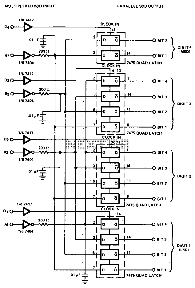
The converter is composed of four quad bistable latches that are activated in the correct sequence by the digit strobe output from the LD110. The complemented outputs (Q) of the quad latch set represent the state of the bit...
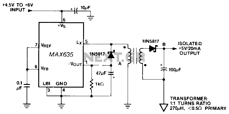
In this circuit, a negative output voltage DC-DC converter generates a -5 V output at pin A. To achieve -5 V at point A, the primary of the transformer must fly back to a diode drop that is more...
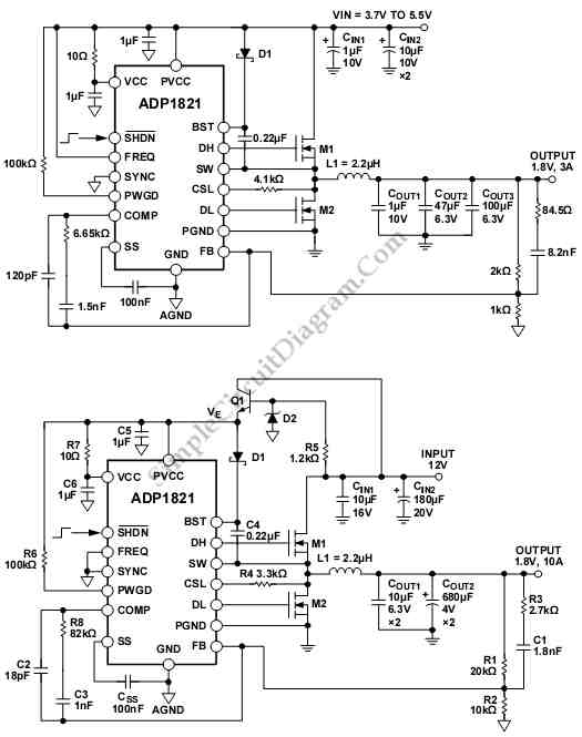
The schematic diagram below illustrates an ADP1821 Step Down DC-to-DC Converter circuit. This circuit employs the ADP1821, which is capable of regulating an output with a load exceeding 20 A, contingent upon the careful selection of power components such...
The circuit allows for various combinations of input voltages (Vin) and output voltages (Vout). The current case under debugging involves Vin=3.6V and Vout=7.2V, with a load represented by a 120-ohm resistor. The calculated duty cycle is D=0.5, indicating 50%,...
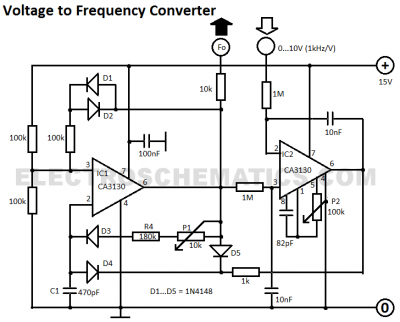
This voltage-to-frequency converter circuit features a voltage-controlled oscillator with a small deviation of 0.5%. The integrated circuit IC1 operates as a multivibrator. The voltage-to-frequency converter circuit is designed to convert an input voltage into a corresponding frequency output. The core...
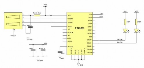
Some still remember the serial RS232 port, also referred to as a COM PORT, as its functionality has largely been replaced by USB ports. However, for electronics engineering students and technicians learning about computer interfaces, the RS232 port remains...