
Voltage to Frequency Converter Circuit

The voltage-to-frequency converter circuit is designed to convert an input voltage into a corresponding frequency output. The core of this circuit is a voltage-controlled oscillator (VCO), which generates a frequency that varies with the input voltage. The precision of this circuit is highlighted by the low deviation of 0.5%, ensuring that the output frequency closely tracks the input voltage.
IC1, serving as the multivibrator, is typically configured to produce a square wave output. In this application, it is used to establish the oscillation frequency based on the control voltage applied to it. The multivibrator configuration can be either astable or monostable, depending on the desired output characteristics. In an astable configuration, the circuit continuously oscillates between two states, while in a monostable configuration, it generates a pulse in response to a triggering event.
Additional components may include resistors and capacitors that set the timing characteristics of the multivibrator, influencing the frequency range and stability of the output signal. The design may also incorporate feedback mechanisms to enhance linearity and minimize distortion in the frequency output.
This voltage-to-frequency converter can be utilized in various applications, including analog-to-digital conversion, frequency modulation, and signal processing, where precise frequency control is essential. The circuit's performance can be further optimized by selecting appropriate passive components and ensuring the power supply is stable, as variations in supply voltage can affect the VCO's output frequency.This voltage to frequency converter circuit has an oscillator that is voltage controlled and has a small, 0.5% deviation. IC1 function as a multivibrator a. 🔗 External reference
Related Circuits

This is a simple basic design of a servo motor controller with a pulse generator. It utilizes the CMOS IC 7555 in astable mode to generate pulses for driving the motor. The servo motor controller circuit employs the CMOS IC...
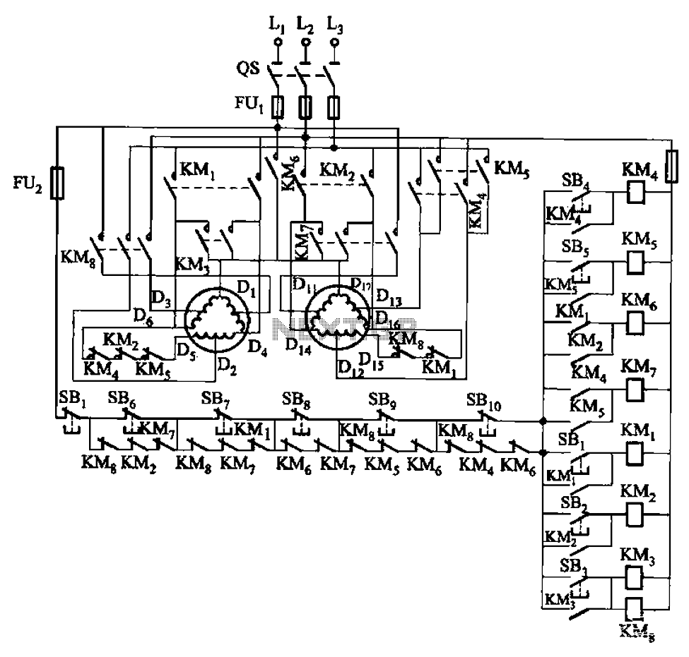
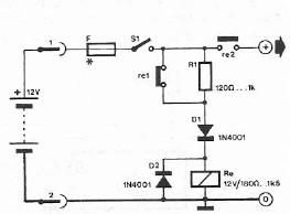
The circuit depicted in Figure 3-120 allows for the control of a motor with a capacity of less than the rated current of 5A by using an intermediate relay instead of a contactor. This circuit enables four forward running...
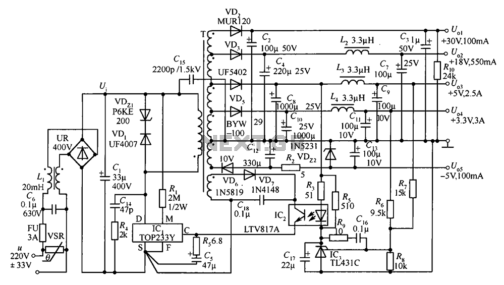
A 35W switching power supply circuit designed for a set-top box output is depicted in Figure 5. It features five distinct voltage outputs: Uo1 (+30V, 100mA), Uo2 (+18V, 550mA), Uo3 (+5V, 2.5A), Uo4 (+3.3V, 3A), and Uo5 (-5V, 100mA)....
The back of the electret microphone resembles the drawings of the CUI Inc part number CMA-4544PF-W, which will be included in the parts kit. While debugging the data logger software on Windows, an oscilloscope practice lab was conducted using...
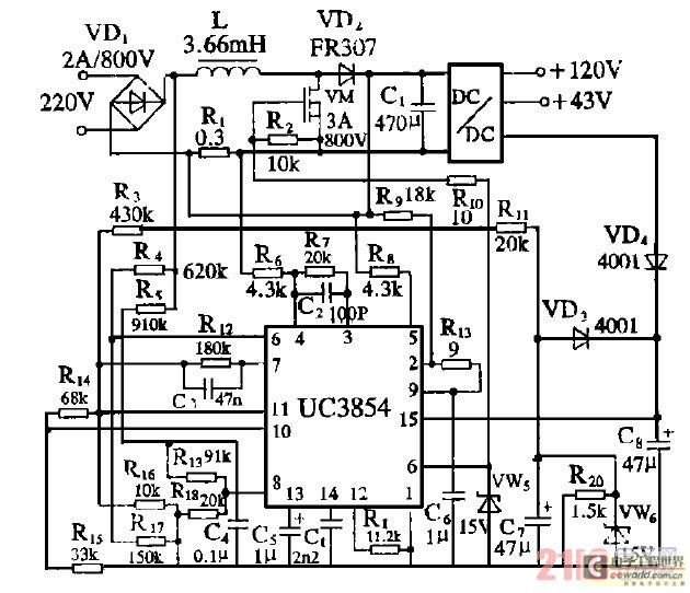
Improve the power factor (PF) to enhance energy conservation in electrical equipment. With advancements in electronic technology, high-frequency active power factor correction (PFC) technology has been increasingly applied across various power systems. The switching power supply of large-screen color...
Safety polarity connection circuit design using common electronic components The safety polarity connection circuit is designed to ensure that electronic devices are connected with the correct polarity, preventing damage from reversed connections. This circuit typically employs common electronic components such...