
Modification of a telescope motor controller for autoguiding

The modification of the SkyWatcher EQ5/EQ4 motor controller to enable autoguiding through a PC's parallel port represents a significant enhancement in telescope control. This integration allows for precise adjustments in the Right Ascension (RA) and Declination (Dec) axes, facilitating long-exposure astrophotography and tracking celestial objects with increased accuracy. The use of the ULN2003 IC in this modification is particularly advantageous, as it provides a reliable interface between the parallel port signals and the microcontroller inputs, ensuring that the manual controls remain functional even when the PC is connected.
The design employs pull-up resistors to maintain a stable high signal on the microcontroller inputs when switches are not engaged. This approach minimizes noise and false triggering, enhancing the reliability of the system. The ability to simultaneously use manual buttons and computer control is a significant feature, allowing for flexibility during operation. Users can manually override the computer's commands, an essential function during critical moments of observation or when adjustments are necessary.
Furthermore, the potential compatibility of this modification with other motor controllers expands its utility beyond the EQ5/EQ4 models, making it a valuable resource for a broader audience of amateur astronomers. The documentation encourages experimentation and sharing of results, fostering a community of innovation and improvement in telescope automation.
In conclusion, the outlined modification not only enhances the functionality of the SkyWatcher EQ5/EQ4 motor controller but also exemplifies the integration of modern technology with traditional astronomical equipment, paving the way for more accessible and efficient astronomical observations.This page describes how I have modified my SkyWatcher dual axis EQ5/EQ4 motor controller to allow autoguiding through the parallel port from a PC. The modification allows the RA+, RA-, Dec+ and Dec- buttons to be activated from the PC via the parallel port and a cheap IC.
I have tested the modification together with K3CCDTools v3. 0. 1 with good res ults (see bottom of this page). There is a good chance that the modification will also work with other controllers. In particular, the SkyWatcher EQ3-2 and the Orion "TrueTrack" controllers seem to be almost identical to the one I modified. A procedure for verifying if the modification shown here is likely to work with a different controller is described here.
I would be glad to hear from you if you have success with modifying a different type of controller, (e-mail address at the bottom of this page), and I would be glad to include the information (and credits) here. Warning: You may use the following information on your own risk. There is always a risk that your equipment can be damaged when you follow procedures like the ones described below.
The author is not responsibility for any damage to your computer, motor controller or other equipment. The navigation buttons on the EQ5/EQ4 controller keyboard are implemented as switches which are closed (become connected) when they are pressed down.
Each switch is connected to ground on one side and to the microcontroller on the other side (on the main circuit board). The inputs to the microcontroller are also connected to +5V via pull-up resistors. When the switch is pressed down the microcontroller senses that the corresponding input signal changes from +5 V to ground, and the signals to the stepper motors are changed accordingly.
The modification uses four out of seven available driver circuits inside an IC called ULN2003 ( datasheet ). When one of the signals from the parallel port (usually a DSUB-25 connector) goes high, the corresponding ULN2003 output pin is shorted to ground (pin 8) via an internal transistor.
The ULN2003 output pin is connected to the microcontroller side of one of the navigation buttons, and the corresponding input signal to the microcontroller is therefore also pulled to ground. The PC program that controls the parallel port can therefore navigate with the motors in the same way as a person manually operating the buttons.
If the parallel port cable is disconnected the ULN2003 will operate as if the input pins were grounded, and there should be no effect of the modification. It is also possible to use the pushbuttons while the computer is connected. If the computer tries to guide the telescope in one direction while you press the button for another direction the effect will be the same as if you pressed two buttons at the same time.
Pictures of the controller are shown below. The label on the back says "DUAL EQ4", but the controller is sold for use either with EQ4 or EQ5. The white cables seen on the left are connected to the RA and Dec motors. The gray cable transmits the guiding signals from the PC parallel port. You can also see the socket for connecting the 6V battery pack. Above you see the inside of the controller. A circuit board with four pushbuttons is mounted on the top, serving as the keyboard. The main circuit board is mounted below with the microcontroller and driver circuitry for the motors. To open the controller you pull out the white buttons with the tip of a screwdriver and remove the screws, including the upper screw holding the 6V power connector.
(The blue and yellow wires coming out of the box together with the PC cable belongs to another project. Also the pushbutton and switch at the right hand side belong to the other project. Please ignore. ) The keyboard can be unscrewed and turned around, as in the picture below. The modification circuit is seen at the bottom left. A surface mount version of the ULN2003 was soldered onto a 🔗 External reference
Related Circuits
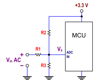
The ATtiny24 microcontroller's ADC is utilized to record an AC signal, which operates within a voltage range of 0 to 3.3V. A precision rectifier is employed to eliminate the negative portion of the signal. The circuit incorporates an LMC6484...

Car and Motorcycle Battery Tester Circuit. Going camping today often requires bringing various electronic devices for daily activities or entertainment. Typically, a charged lead-acid battery and a power source are essential. The Car and Motorcycle Battery Tester Circuit is designed...
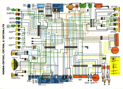
Many inquiries arise regarding motorcycle wiring, particularly among individuals attempting to repair their blinkers or seeking to streamline electronics for custom builds. A crucial aspect of constructing any chopper, bobber, cafe racer, brat bike, or rat rod involves eliminating...
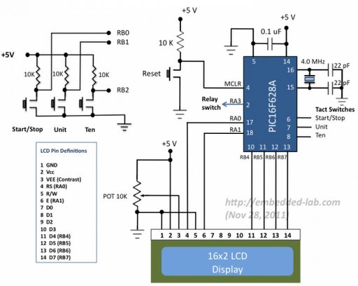
A source code for a simple PIC-based digital timer is provided. The hardware for the project is not available; however, it will be demonstrated using a DIY PIC16F628A breadboard module and I/O board. The complete circuit diagram and firmware...
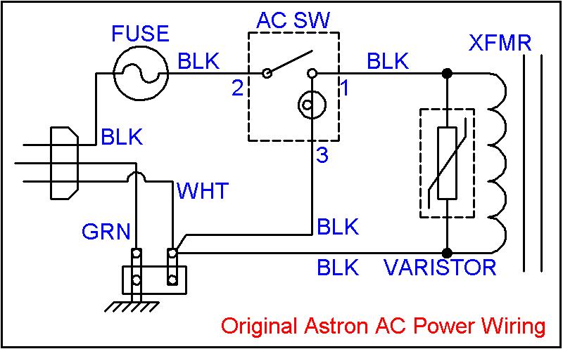
The regulated output voltage fluctuated as the unregulated DC voltage changed, which in turn varied with the load current or the incoming AC line voltage. There was no straightforward solution to the existing circuit that would rectify this issue....
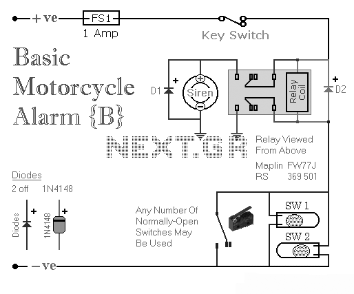
Two simple relay-based motorcycle alarm circuits. These are easy to build and can be used to protect motorcycles, but they also have many other applications. If relays with 6-volt coils are used... The motorcycle alarm circuits described consist of two...