
Moisture detector

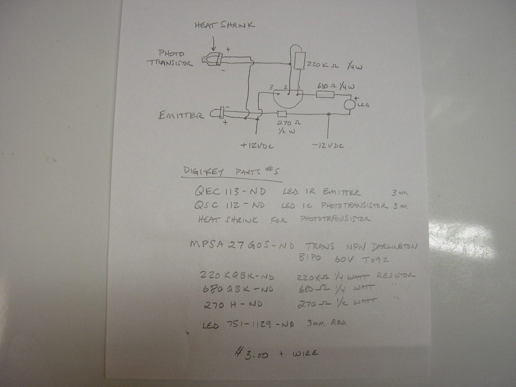
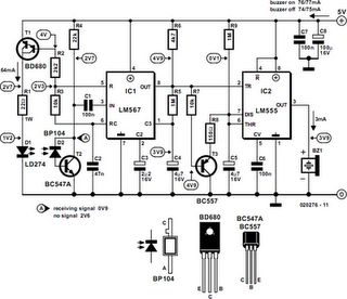
The described moisture detector employs a simple yet effective design utilizing fine wires arranged in parallel with a specified spacing. This configuration allows for the detection of moisture between the wires, which serves as the primary sensing mechanism. When moisture bridges the gap between any two wires, it completes an electrical circuit, triggering an alarm system, typically in the form of a horn or buzzer.
The circuit can be powered by a DC power supply, which is essential for the operation of the alarm. The alarm will remain active as long as moisture is detected. To turn off the alarm, the DC power supply must be disconnected, which interrupts the power flow to the circuit and silences the horn.
For practical implementation, the circuit may include additional features such as a resistor to limit current flow, a diode for reverse polarity protection, and possibly a transistor to amplify the signal for the alarm. The spacing of the wires can be adjusted based on the application requirements, allowing for sensitivity tuning to detect varying levels of moisture. Furthermore, the entire assembly can be enclosed in a protective housing to prevent false alarms from environmental factors such as dust or debris while ensuring reliable operation in intended conditions.
Overall, this moisture detection system is straightforward and can be easily integrated into various applications, including agricultural monitoring, home safety systems, or industrial environments where moisture levels need to be controlled.The detector is made of fine wires spaced about one or two inches apart. When the area between a pair of wires becomes moistened, the horn will sound To turn it off, dc power must be disconnected.
Related Circuits
Model Railroader is the world's largest magazine on model trains and model railroad layouts. It offers assistance for both beginners and advanced enthusiasts across all model railroading scales, including layout track plans, product reviews, news, and forums. Model Railroader magazine...
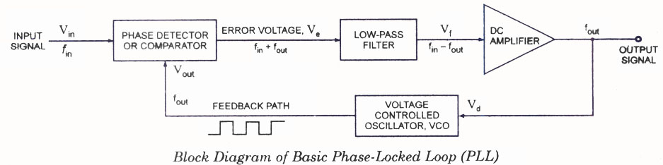
The operating principle of a Phase Locked Loop (PLL) is illustrated with a block diagram that includes a Phase Detector, Voltage Controlled Oscillator, and Low Pass Filter. A Phase Locked Loop (PLL) is an essential electronic circuit used in various...
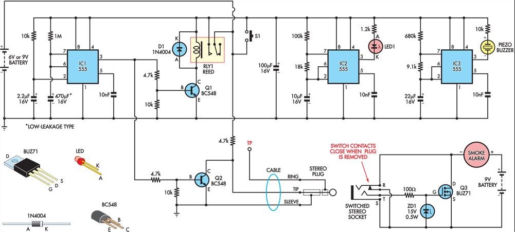
This circuit provides a method for temporarily silencing a battery-powered smoke detector after incidents such as burning toast or cooking mishaps. Unlike earlier designs, this advanced version does not produce unintended chirps or whistles at the end of the...
This metal detector schematic circuit is based on a transistor radio as a detector. This metal detector is entirely different from other metal detectors because this circuit does not have a speaker. With the radio tuned to a weak...
This circuit can be constructed using readily available low-cost components, some of which may be found in a junkbox. The specified value of 22 ohms for resistor R1 results in an average current of approximately 65 mA through the...
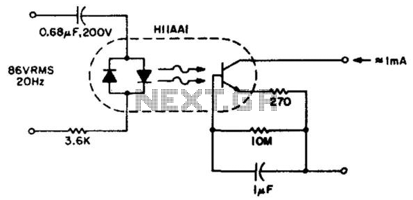
This circuit detects the approximately 20-Hz, 86-Vrms ring signal on telephone lines and initiates action in an electrically isolated circuit. Typical applications include automatic answering equipment, interconnect/interface systems, and key systems. The detector is designed to be simple and...