
Simple Ring Detector

This circuit functions as a ring signal detector, specifically tuned to recognize the ringing voltage typically present on telephone lines. The design incorporates an isolated circuit to ensure that any connected devices are protected from voltage spikes and noise that may be present on the line. The 20-Hz frequency is characteristic of standard telephone ringing signals, and the circuit is calibrated to respond accurately to this frequency while ignoring other signals that may be present.
The primary component of the circuit is a detection mechanism that can sense the 86-Vrms ring signal. Upon detecting this signal, the circuit activates a relay or a similar output device, which can control various applications such as automatic answering systems that respond to incoming calls. The simplicity of the detector allows for easy integration into existing systems without the need for complex configurations.
The circuit's output is designed to provide a 1-mA signal, which is sufficient to trigger devices that operate on a 7-mA line load. The timing aspect of the circuit is managed by a time-delay capacitor, which not only helps in suppressing unwanted dial-tap noises and clicks but also ensures that the output is stable and does not respond to transient signals. This capacitor filters out the zero crossing of the 20-Hz wave, allowing the circuit to reliably detect the start of the ring signal without false triggers.
In summary, the ring signal detection circuit is an essential component for applications that require reliable identification of incoming calls while maintaining electrical isolation and minimizing noise interference. Its straightforward design and effective filtering capabilities make it suitable for various telecommunications applications. This circuit detects the 20-Hz approximately 86-Vrms ring signal on telephone lines and initiates action in an electri cally isolated circuit. Typical applications include automatic answering equipment, interconnect/interface and key systems. The detector is the simplest and provides about a 1-mA signal for a 7-mA line, which loads for 0.1 s after the start of the ring signal. The time-delay capacitor provides a degree of dial-tap and click suppression, and filters out the zero crossing of the 20-Hz wave.
Related Circuits
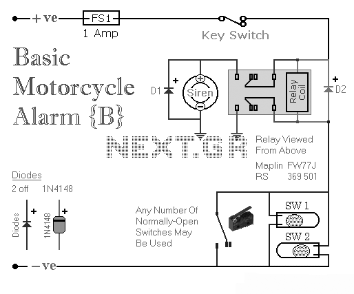
Two simple relay-based motorcycle alarm circuits. These are easy to build and can be used to protect motorcycles, but they also have many other applications. If relays with 6-volt coils are used... The motorcycle alarm circuits described consist of two...
A six-year-old child and an adult viewed a project on YouTube and captured an image of it using the print screen function to create a similar design. The project likely involves a basic electronic circuit that can be replicated easily,...
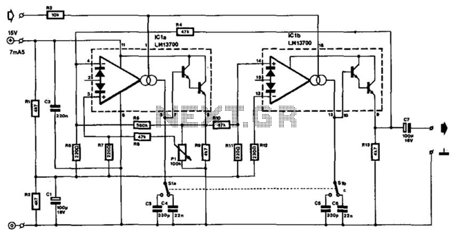
The frequency of this sine-wave oscillator is determined by a direct voltage, U, ranging from 0 to 15 V. The distortion in output signals of up to 10 Vpp does not exceed 1%. When the output is reduced using...
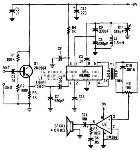
Using an NE602 heterodyne detector and U1 as an RF amplifier, this receiver tunes the middle portion of the low-frequency spectrum from 150 to 250 kHz. U2 is a loudspeaker amplifier. The described circuit employs an NE602 integrated circuit...
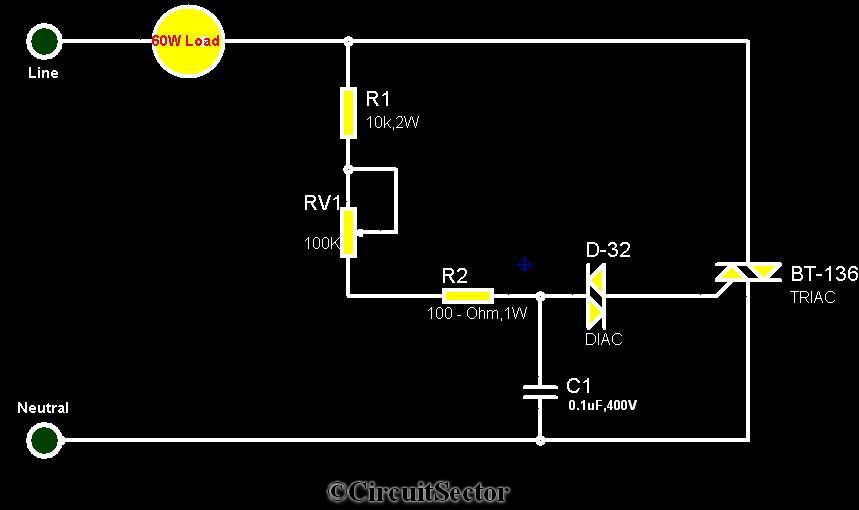
The circuit diagram presented is a triac-diac electronic fan regulator designed to reduce power consumption of electric fans, even at low speeds. Traditional resistor-inductor fan regulators tend to generate excess heat, wasting energy when the fan operates at lower...
A schematic diagram of a fast pulse detector is shown in the figure below. An error detection rate of under 10% can be expected for a 60 ns pulse to achieve error-free operation. The fast pulse detector circuit is designed...