
MORSE CODE OSCILLATOR

The circuit design incorporates a 555 timer configured in astable mode, which continuously oscillates between high and low states, producing a square wave output. The frequency of oscillation is primarily set by the resistors R1 and R2 in conjunction with the timing capacitor C1, where the duty cycle can be adjusted by varying R2, the potentiometer. This flexibility allows the user to modify the tone produced by the circuit, making it suitable for various applications, such as sound effects or alarms.
The output from the 555 timer is fed into the LM386 audio amplifier (IC2) through the coupling capacitor C2, which blocks any DC offset and allows only the AC signal to pass. The LM386 is a low-voltage audio amplifier capable of driving small speakers, making it ideal for battery-operated devices. The gain of the LM386 is fixed, typically around 20, which means that the overall volume output is directly related to the loudspeaker's specifications. Choosing a speaker with higher wattage will result in a louder output, while a lower wattage speaker will produce a quieter sound.
The switch S1 serves as the activation mechanism for the entire circuit, allowing the user to start the oscillation and sound generation process. Upon pressing the switch, the circuit powers up, and the 555 timer begins its oscillation, generating audio signals that are amplified by the LM386 and subsequently output through the connected loudspeaker. The simplicity of this circuit makes it an excellent choice for educational purposes, as well as for hobbyist projects where sound generation is required.The circuit is built around a 555 oscillator (IC1) and an LM386 audio amplifier (IC2). The 555 circuit is an astable oscillator, with the chip output retriggering the circuit. When the key (S1) is pressed, it activates the circuit. The 555 oscillates at a frequency determined by R1, R2, and C1. Potentiometer R2 is used to adjust the tone frequency of the oscillator. Some of the output current of IC1 is coupled to IC2 via a 10- °F capacitor, C2, so that it will be sufficient to drive a loudspeaker. Because the circuit has no gain control, the volume depends on the size and wattage of the speaker. 🔗 External reference
Related Circuits
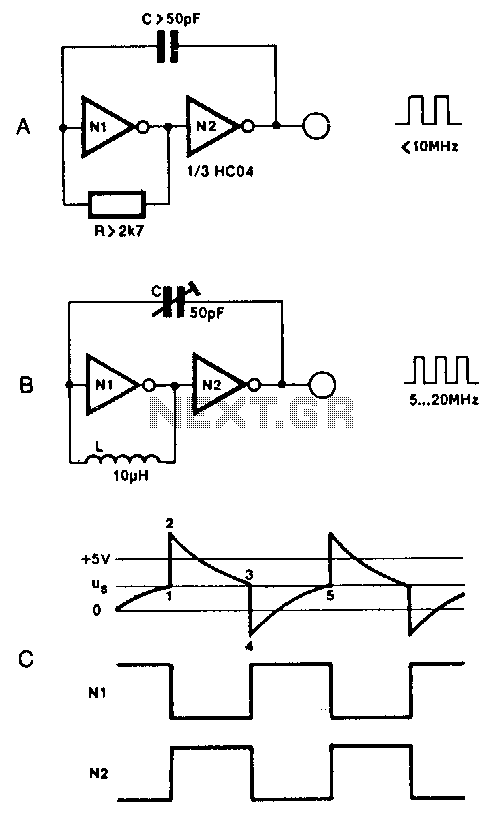
Two inverters, one resistor, and one capacitor are sufficient to create an HC(T)-based oscillator that operates reliably up to approximately 10 MHz. The use of two HC inverters results in a fairly symmetrical rectangular output signal. In this configuration,...
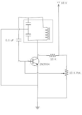
The frequency remains stable as the voltage decreases. It is referred to as the "backwards JT" because it operates optimally with a bifilar coil and a single transistor. With a modification to the circuit, it is possible to deplete...
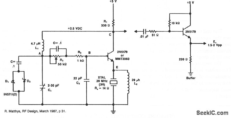
A typical circuit operating at 20 MHz is presented. The crystal, which possesses an internal series resistance (RS) of 14 ohms, oscillates at its third harmonic. Diode clamps D1 and D2 provide constant amplitude control. The transistor functions continuously...
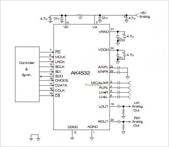
AMIS-49200-XTP is a subpackage of AMIS-492X0. For further information, please refer to the description of AMIS-492X0. The datasheet for AMIS-49200-XTP can be downloaded from the link provided below. By ON Semiconductor. The AMIS-49200-XTP is a specialized integrated circuit designed for...
This CMOS square-wave oscillator utilizes the 4047 multivibrator circuit, suitable for both monostable (one-shot) and astable applications. In the provided configuration, the 4047 operates as an astable multivibrator. The circuit features three outputs from the 4047, with the first...
A phase-shift audio oscillator exhibits excellent distortion characteristics due to "softened" diode limiting provided by the 1N914 diode and a resistor divider, along with degenerated gain facilitated by a 68-ohm emitter resistor. To minimize distortion, it is recommended to...