
Audio Oscillators

This circuit can be constructed in a compact style and encapsulated with epoxy mixed with model airplane paint for a professional finish. A two-transistor Wien bridge oscillator utilizing a standard night-light bulb for stabilization is also described, producing an output of about 6 volts peak-to-peak, capable of driving fixed loads as low as 2 or 3 thousand ohms without additional buffering. An amplitude potentiometer of 10k, with its wiper connected to a high input impedance output amplifier, serves as an excellent load. Distortion is minimized by adjusting a 1k feedback potentiometer until the output amplitude is approximately one volt below the maximum level, with the potentiometer set to its highest resistance. It is advisable to wait a few seconds between adjustments to allow the bulb to stabilize, as the audio signal heats the filament, thereby increasing resistance and controlling loop gain. The circuit can vary frequencies from a few Hertz to over 60 kHz by selecting capacitor values between 1 µF and 47 pF, with the frequency being approximately 1/(6.28 x RC). Resistor values may also be adjusted for additional frequency range, but extreme values may introduce issues. A 7-watt bulb can be substituted with a smaller type with a similar resistance (greater than 50 ohms), although the larger filament's long time constant is beneficial for generating very low frequencies. The circuit typically draws between 18 and 45 mA, influenced by the transistor gain and resistor values, with current outside this range potentially leading to distortion. The 1.2k emitter resistor can be slightly varied to achieve a target current consumption of 25 to 30 mA. It is noteworthy that operational amplifiers can effectively serve as Wien bridge oscillators without significant impedance and bias concerns, with numerous designs available in online resources and manufacturer application notes. However, in many cases, simple transistor configurations are equally effective.A phase-shift audio oscillator with excellent distortion characteristics thanks to "softened" diode limiting provided by the 1N914 and resistor divider and degenerated gain provided by the 68 ohm emitter resistor. For minimum distortion, increase the 68 ohm resistor to a point just below where oscillation stops. A simple buffer may be adde d for driving lower impedance loads. The output amplitude will be about 5 volts p-p but one of the 1N914`s 10k divider resistors may be changed for a different output amplitude. The circuit will work well with a power supply voltage other than 9 volts but the 68 ohm resistor may need adjustment.
I just finished watching "Track Down, " a movie about the hacker, Kevin Mitnick. In the movie, Mitnick steals a bunch of files from a phone company named Nokitel and is looking down the list when one catches his eye. He goes back and opens it. The schematic below is what he sees! Wow, those are some valuable files he has there. I`ve been hacked by a movie about a hacker! I`m not sure how to feel about that. I`ve added a bypass cap and used a different diode symbol since the movie, but it`s mine. In the movie that schematic enabled him to convert his phone into a local scanner. I can`t say I`ve tried it. : ) Too bad it took me 12 years to see this. My 1. 5 seconds of fame is long gone. The circuit can be built in the "blobular cluster" style (to coin a phrase) and potted with epoxy mixed with a little model airplane paint.
Use quick-setting epoxy and, holding the circuit by the legs, keep rotating the blob near the end of the cure cycle to get an even coat - quite an art form! The finished module looks quite professional, not unlike many dipped caps. Here is a two-transistor Wien bridge oscillator using an ordinary night-light bulb for stabilization.
The output is about 6 volts p-p and can drive fixed loads as low as 2 or 3 thousand ohms without additional buffering. A 10 k amplitude potentiometer with the wiper going to a high input impedance output amplifier would make an excellent load.
Excellent distortion is achieved by adjusting the 1 k feedback potentiometer until the output amplitude is about a volt less than the maximum level (with the pot set to the highest resistance). Wait a few seconds between adjustments to give the bulb time to stabilize; the audio signal actually heats the bulb`s filament causing the resistance to go up which controls the loop gain.
You will see the signal bounce a little as the bulb gains control. This simple version of the popular Wien bridge oscillator uses feedback to hold the junction of the two RC networks (base of first transistor) near zero volts (100 mV p-p) and the ends of the RC networks move in opposite directions like a see-saw. With the resistor values shown, the frequency may be varied from a few Hz to over 60 kHz by selecting a value for C between 1 uF and 47 pF.
The frequency will be reasonably close to 1/ (6. 28 x RC). R may be varied also for additional range but values too low or high may cause problems. The 7-watt bulb may be replaced by a smaller type with similar resistance (more than 50 ohms) but the long time constant of the larger filament is helpful when generating very low frequencies. The circuit should draw between 18 and 45 mA, a value determined by the transistor gain and the value of R.
Current outside of this range may cause distortion. The 1. 2 k emitter resistor may be varied slightly to adjust the current consumption; shoot for 25 to 30 mA. It should be noted that op-amps make great Wien bridge oscillators without significant impedance and bias concerns!
There are dozens on the web and in manufacturers` application notes. But sometimes a couple of friendly transistors fit the bill perfectly. 🔗 External reference
Related Circuits
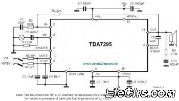
The IC TDA7295 is a monolithic integrated circuit designed for use as an audio class AB amplifier in high-fidelity applications, including home theaters and high-end televisions. The TDA7295 is a versatile audio amplifier that delivers high-quality sound reproduction, making it...

This is a simple design of an audio level meter. The circuit utilizes a single integrated circuit (IC) and a minimal number of external components. It is based on the LM3915, which functions as the controller for the audio...
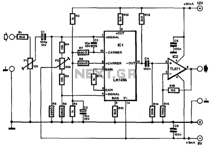
Often, the frequency of a signal must be doubled, and the modulator/demodulator chip LM1496 serves as an ideal basis for this application. From trigonometry, it is well known that 2sin(x)cos(x) = sin(2x) and sin^2(x) = 1 - cos^2(x). These...
Below is the schematic diagram of an audio input module. This module is capable of producing a DC output voltage that is proportional to the amplitude of the input signal. The audio input module typically consists of several key components...

This circuit is designed as a pocket-sized, high-performance audio oscillator. It can operate using a battery-powered version, which is feasible at a very low cost by utilizing a single quad op-amp to provide the entire active circuitry. The design...
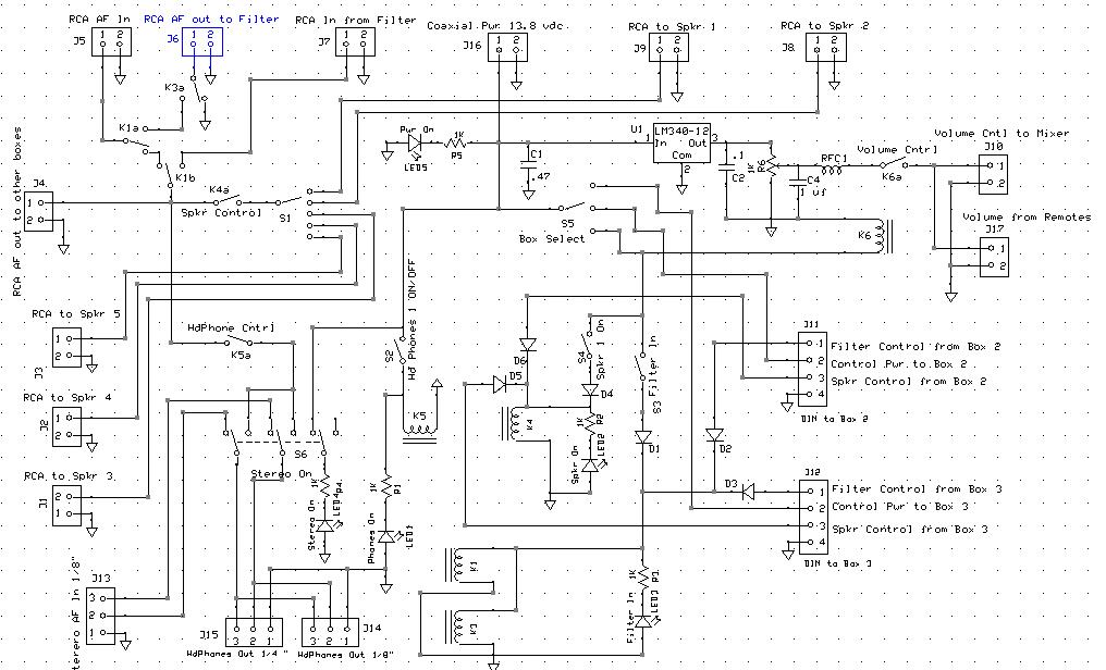
An audio mixer receives outputs from various audio sources and amplifies them to drive a common speaker, allowing all active radios to be heard through a single speaker. However, there is a need for a master Audio On/Off switch...