
mosfet 500 watt inverter with solar battery charger controller

The inverter circuit comprises two primary sections: an oscillator circuit and a MOS driver circuit. The oscillator circuit is crucial for generating a high-frequency square wave signal, which serves as the control signal for the subsequent stages of the inverter. It operates on the principle of Pulse Width Modulation (PWM), where the duty cycle of the output signal can be adjusted to control the output voltage and power delivered to the load.
In the oscillator section, components such as resistors, capacitors, and operational amplifiers are configured to establish the desired oscillation frequency. The output of this section is a square wave that alternates between high and low states, which is essential for the operation of the inverter.
The second section, the MOS driver circuit, is responsible for amplifying the signals produced by the oscillator. It utilizes MOSFETs (Metal-Oxide-Semiconductor Field-Effect Transistors) to switch the output effectively. The driver circuit ensures that the MOSFETs are turned on and off at the correct times, allowing for efficient power conversion from DC to AC.
Together, these sections form a complete inverter circuit capable of converting a DC input into a usable AC output, making it suitable for various applications, including renewable energy systems, uninterruptible power supplies (UPS), and motor drives. The design emphasizes efficiency, reliability, and the ability to handle varying load conditions while maintaining stable operation.Circuit No. 1 (Oscillator Circuit and feedback circuit) Circuit No. 2 (MOS DRIVER CIRCUIT) FINAL PRODUCT: - WORKING OF THE CIRCUIT No.1 (Oscillator Circuit and feedback circuit) This Inverter is based on the Pulse Width Modulation technology. Working principle of various section of this INVERTER is explained next:- 1.Oscillator section:- This section generates the..
🔗 External reference
Related Circuits
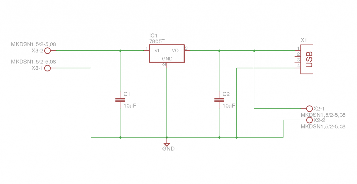
This document outlines the details of several circuits designed and built for a robot. The first circuit is a voltage regulator intended to supply power to a Raspberry Pi from a 7.2V battery. While the circuit is relatively simple,...
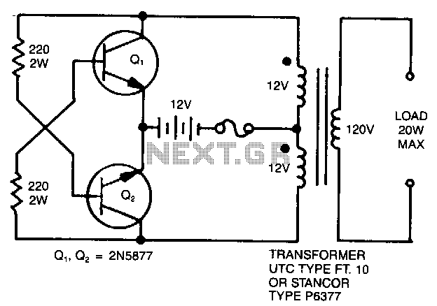
A simple 120 V to 24 V center-tapped control transformer, along with four additional components, can accomplish the task. This circuit produces a clean 200 V peak-to-peak square wave at 60 Hz and is capable of supplying up to...
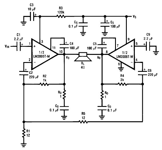
A simple 20-watt amplifier electronic project can be designed using the LM2005 dual high-power amplifier, which is engineered to provide optimal performance and reliability for automotive applications. The LM2005 20-watt amplifier has a high current capability of 3.5A, allowing...

This circuit is designed for an RF (radio frequency) transmitter experiment, where a watt meter is instrumental in optimizing the transmitter circuit. A simple RF watt meter circuit is illustrated in the schematic diagram below. The circuit is not...
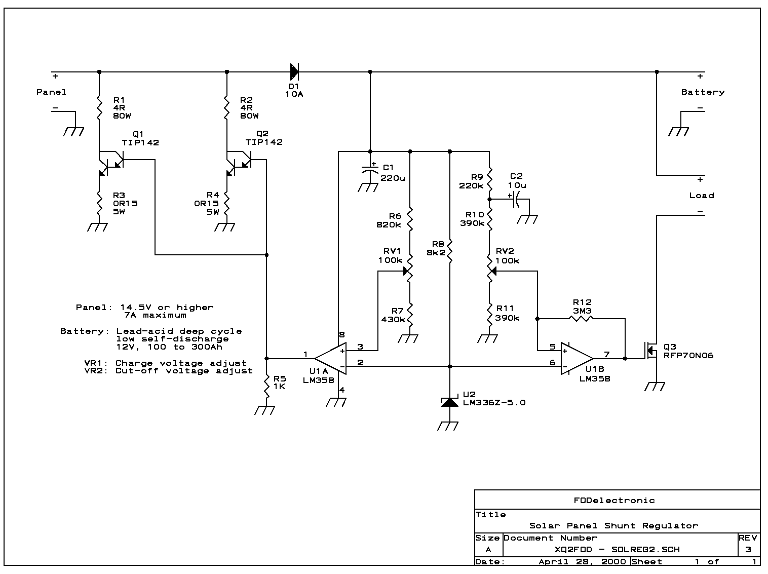
The circuit presented here uses linear shunt regulation. Simply spoken, it burns off all excess energy from the panel, keeping output voltage constant. At times when the solar panel output is equal or greater than the load, and the...
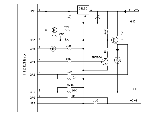
This device is built around a PIC12F675 (a dandy little part from Microchip). The number of cells (1 to 8) is programmed in using the one button. The cell count is saved in EEPROM the next time you power...