
Mosfet Amplifier 20Watt Output Power Schematic Diagram

The TDA1308 and TDA1308A are integrated circuits specifically designed for audio amplification, making them suitable for portable devices such as MP3 players, portable speakers, and other battery-operated audio equipment. The class-AB configuration provides a good balance between efficiency and audio quality, allowing for minimal distortion while delivering sufficient power output for driving headphones or small speakers.
The circuit typically includes input capacitors to block any DC offset from the audio source and coupling capacitors at the output to prevent DC from reaching the load. Feedback resistors are employed to set the gain of the amplifier, allowing users to adjust the output level according to their requirements. Additionally, bypass capacitors are often included near the power supply pins of the TDA1308 or TDA1308A to ensure stable operation and reduce noise.
For optimal performance, it is crucial to adhere to the recommended power supply specifications. The use of a regulated power supply is advised to maintain a consistent voltage level, which is essential for achieving the desired output power and audio clarity. Furthermore, thermal management should be considered, especially in compact designs, to prevent overheating during prolonged operation.
Overall, this audio amplifier circuit is a practical solution for enhancing audio output in portable applications, offering versatility and efficiency in a compact form factor.This audio amplifier showed in this circuit diagram, is a very simple and efficiency audio amplifier circuit based on the TDA1308 integrated class-AB stereo headphone. The device is fabricated in a 1 mm Complementary Metal Oxide Semiconductor (CMOS) process and has been primarily developed for portable digital audio applications.
You can use thi s circuit diagram with TDA1308 or TDA1308A, the difference between the TDA1308 and the TDA1308A is that the TDA1308A can be used at low supply voltages. The maximum output power that can be obtained with this circuit is around 80mwatts. This audio amplifier circuit requires a very low voltage power supply : from 3 to 7 volts for single supply or 1.
5 to 3 volts for dual supply, for TDA1308. The TDA1308A supports a low voltage input down to 1. 2 volts, but the typical power supply required for both circuits is 5 volts for single supply and 2. 5 volts for dual supply. You are reading the Circuits of Mosfet Amplifier 20Watt Output Power And this circuit permalink url it is 🔗 External reference
Related Circuits
A low power FM pirate radio. The output power is approximately +35 dBm (3.16 watts) over a 50-ohm load and operates on a +24-volt power supply. The project consists of a Hartley oscillator (modulated VCO) and three stages (Class...
The circuit is a MOSFET based linear voltage regulator with a voltage drop of as low as 60 mV at 1 ampere. Drop of a fewer millivolts is possible with better MOSFETs having lower RDS(on) resistance. The circuit uses...
The tape output circuit processes the left and right channel signals through a first buffer amplifier. The output signal is split into two paths: one route directly connects to an amplifier for amplification, while the other route passes through...
This is the first version of a laser diode power supply and current source using an n-channel power device. Components include LM358D IC, transistor, resistor, and others. The described circuit functions as a power supply specifically designed for laser diodes,...
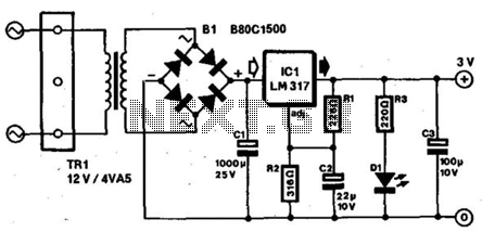
Most small portable radios require a 3-V supply, which is typically provided by two AA or AAA batteries. Many of these radios are equipped with a charger socket since rechargeable batteries are an option. When used in a stationary...
WARNING: Do not touch any part of the circuit when it is running (connected to the power line); this circuit is not isolated from the mains supply. This circuit operates directly connected to the mains supply, which poses a significant...