
LOW POWER FM TRANSMITTER

5 dBm, at my project I used a MWA-130 ( from Motorola) as driver stage. At second stage I used a 2N5109 (Motorola), but you can also use a 2N3866, and at final stage a 2N3553. With proper biasing and setting up the trimmers to maximum output power you can achieve around 2. 8 watts of EIRP using a 0 dBi antenna. A good irradiant system is also important, as well the coax cable that I recommend low loss cables if you are using a long cable distances.
RG-58A haves a 67% of propagation velocity and 21. 65 dB/100m of insertion loss at 146 MHz. I also recommend you use a low pass filter at final stage to prevent harmonics products cause harmful interferences on the MARS/CAP systems. Here in Brazil, many pirate radios don`t use such filter causing many trouble at MARS service. At final you can found many schematics, and of couse a suggested low pass chebyshev filter and the respective response frequency curve.
You will experience a low insertion loss within this filter, but not so expressive. The VCO can operate as free ( open loop) or synthesized (PLL) oscillator, you just must insert a jumper to close the loop for PLL or release it to free oscillator operation. The frequency deviation is controled by varactor diode that change the instrinsic capacitance within the voltage audio input causing a frequency deviation.
Note: set it to ± 75 KHz to FM pattern broadcast operation. Another varactor BB809 control the operation frequency, 200 KHz step increments is allowed at PLL schematic circuit at final of this page, the oscillator was constructed to operate in FM broadcast (88 to 108 MHZ) without any change in components. As hartley oscillator, if you wanna change the operation frequency just change the numbers of turns in the inductors at LC tank circuit.
As you know, decreasing the numbers of turns, you get upper frequencies, and vice-versa. Pay attention to start up the oscillator if you wanna change it to operate in high frequency than FM braodcast. Following the Barkhausen Criteria, we have a feedback in a simple amplifier and also sustain the oscillations, so the K fator( Loop gain) must be equal to one.
The MPF 102 oscillator transistor operates quite good until 150 MHz, a high Ft transistor will be required to high frequency operation. If you could use a network of varactors diode ( paralel association) to control the frequency deviation would be interesting because the BB809 have hyper abrupt curves.
Maybe MV209 in paralel produces less distortion and also ensure more linearity. At input ( audio signal), I did a pre-emphasis network to garantee that modulation index at high audio frequencies ( up 1KHz). At FM radio, the relation S/N depends of modulation index employed. The index decrease as modulation frequency increases, to a constant frequency deviation. Pre-emphasis is a high pass filter, that the cutoff frequency is slight upper of a maximum modulated frequency.
The filter must provide 6dB/octave, that can be stablished by a series capacitor with the patch audio signal. Between the oscillator and driver, a buffer stage was inserted to prevent oscillations and increase isolation, high impedance at gate ( oscillator side) and low impedance at source terminal.
At MAV-11 output there are a sample frequency output to the pre-scaler ( if using PLL), and under the conditions of a high power, I added a resistive PI attenuator of 8 dB, it prevents not overload the pre-scaler input. The driver stage is the own MAV-11 with 12 dB of gain, I choose the 🔗 External reference
Related Circuits
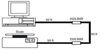
This is the schematic diagram of a 9-Pin RS232 Line Booster Signal Direction. The device functions as a 9-pin RS-232 repeater, re-transmitting all 8 signals while also maintaining the ground line. The 9-Pin RS232 Line Booster is designed to extend...
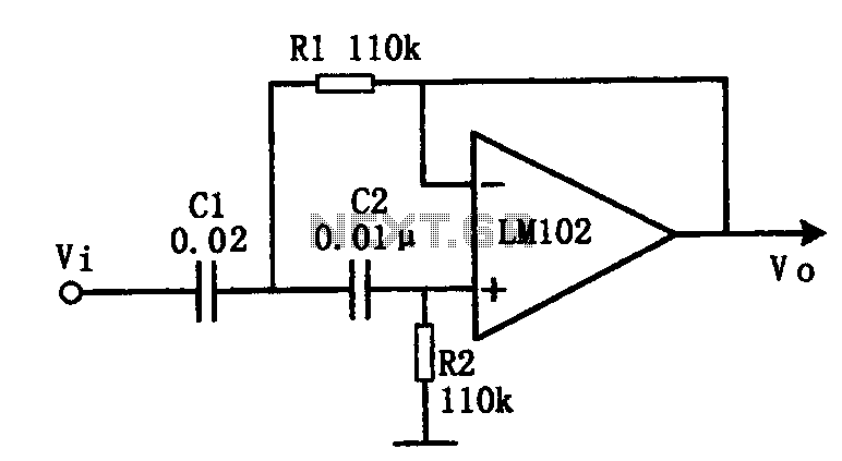
This document presents an active low-pass filter circuit with a cut-off frequency (fc) of 10 kHz. The circuit allows for various values for the ratios of resistors R1 and R2, as well as capacitors C1 and C2. Specifically, it...
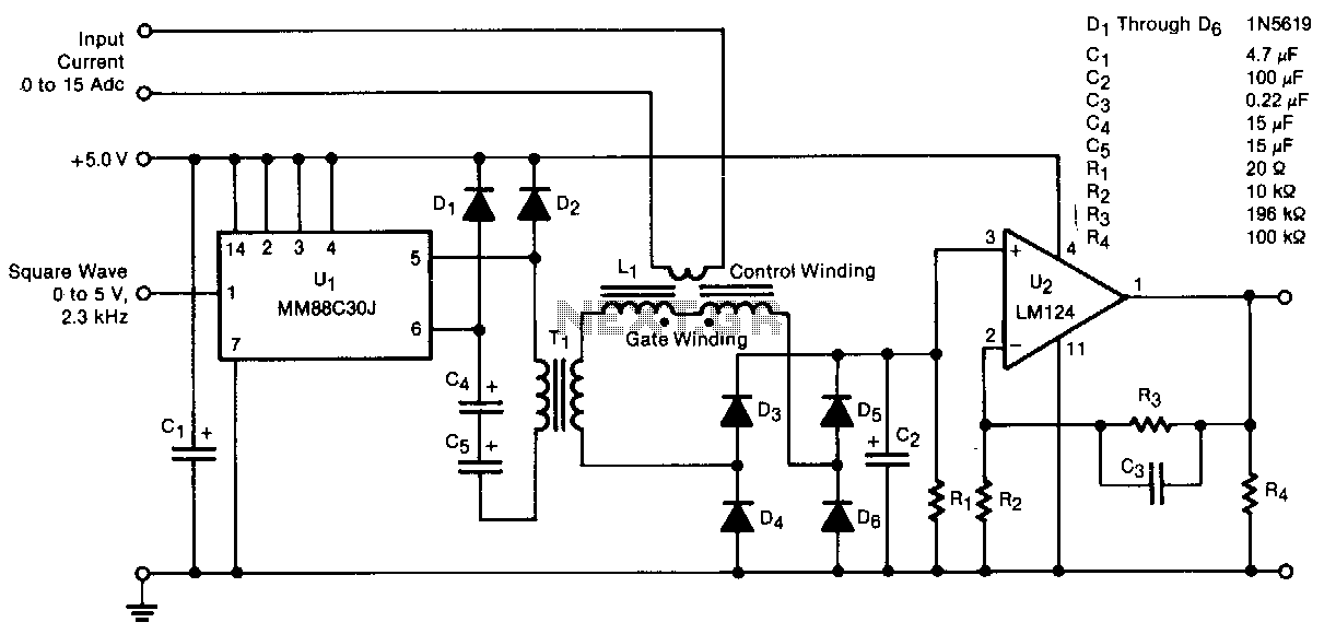
A transducer senses direct current magnetically, providing isolation between the input and the output. The detecting and isolating element is a saturable reactor, through which the input current to be measured passes via a one-turn control coil. The transducer...
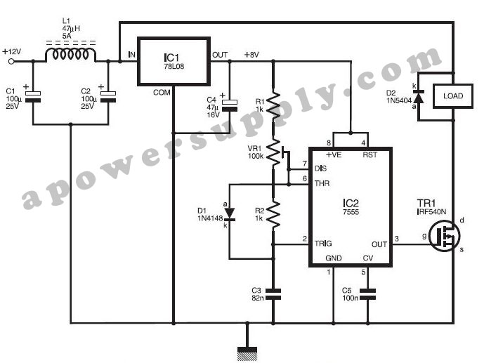
This DC power supply controller is regulated by pulse width modulation (PWM), which is generated by a circuit utilizing timer IC2 7555 according to a specific duty cycle formula. The described DC power supply controller employs a timer IC, specifically...
When the amplifier is installed inside the suitcase, it will require a change to stop working. The LA47536 has a control pin (pin 4) that requires a small voltage of up to 2V to turn on the amplifier. Transistors...
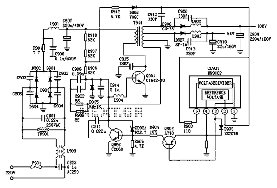
The Hitachi NP8C switching power supply circuit is illustrated in FIG. The Hitachi NP8C power models include CTP236, CEP320D, CRP350D, 450D, Furi HFC-236, 450, and Venus C37-401, C46-1, C563, among others. This circuit was widely used in early Chinese...