
MOSFET-based Joule Thief steps up voltage

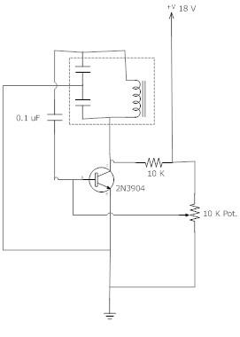
The blocking oscillator circuit is a type of oscillator that operates by inducing oscillations through positive feedback. It typically consists of a transistor, a coil (inductor), a capacitor, and a resistor. The fundamental operation relies on the rapid charging and discharging of the capacitor, which, in turn, influences the magnetic field in the inductor.
In this circuit, when the transistor is turned on, current begins to flow through the inductor, causing it to store energy in the form of a magnetic field. The inductor's property of resisting changes in current results in a gradual increase in current flow. Once the current reaches a certain threshold, the transistor enters saturation, and the magnetic field collapses rapidly. This sudden change in current induces a high voltage across the inductor, following the equation V = L di/dt.
The output voltage can be significantly higher than the input voltage due to this inductive kickback. The oscillation frequency of the circuit is determined by the values of the inductor and capacitor, as well as the characteristics of the transistor. The resistor serves to limit the current and stabilize the operation of the circuit.
The simplicity of the blocking oscillator circuit makes it suitable for various applications, including voltage converters, pulse generators, and signal modulation. It is important to ensure that the components are rated for the expected voltage and current levels to avoid damage and ensure reliable operation. Proper design considerations, such as component selection and layout, can enhance the performance and efficiency of the blocking oscillator circuit.A simple blocking oscillator circuit can be used to step up voltage using properties of coil inductance (V = L di/dt). Such a circuit is shown in Figure 1. 🔗 External reference
Related Circuits
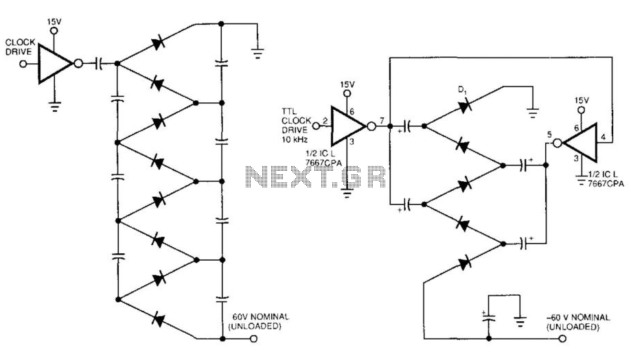
Figure 99-1(a)'s circuit exhibits a high output impedance due to the small effective capacitance of the series-connected capacitors, resulting in considerable voltage loss from the diode drops. This circuit requires two diodes and two capacitors to generate a DC...
A voltage-to-frequency converter can be constructed using the LM231/331 chip, making it a cost-effective solution for applications such as analog-to-digital conversion and frequency-to-voltage conversion over extended periods. The LM231/331 series of voltage comparators can be effectively utilized to design a...
The frequency remains stable as the voltage decreases. It is referred to as the "backwards JT" because it operates optimally with a bifilar coil and a single transistor. With a modification to the circuit, it is possible to deplete...
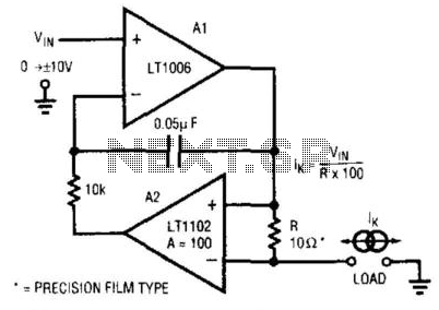
This circuit is a programmable current source that utilizes the LT1102 operational amplifier from Linear Technology Corp. in conjunction with the LT1006 operational amplifier. The first amplifier (A1), biased by a voltage source, drives current through a resistor (R)...
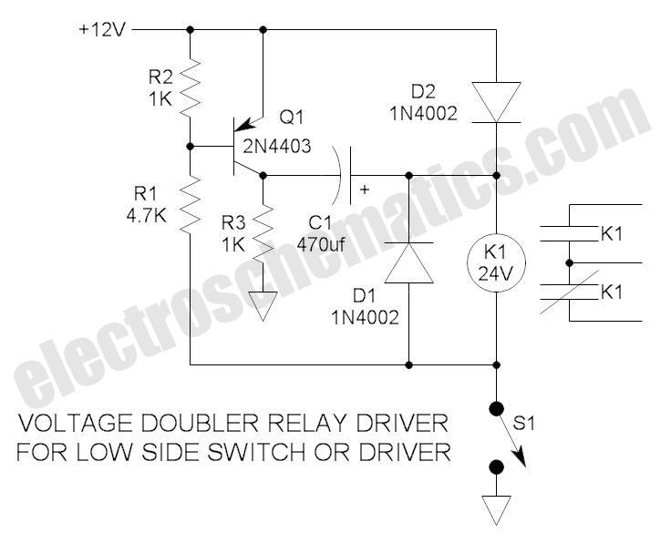
These novel relay driver circuits have the capability to activate a relay with a coil voltage rating that is double the supply voltage (Vcc). Once the relay is activated, the armature is maintained using Vcc, resulting in a significant...
This LM10 circuit can be used as a low voltage, low current voltage source or reference. This circuit regulates the voltage from the power supply to provide a stable output. The LM10 is a precision voltage reference and regulator integrated...