
MOSFET IRF540A circuit

The circuit in question appears to involve a series configuration of light-emitting diodes (LEDs) that require both components to be illuminated for the circuit to be considered complete. This indicates a potential issue in the design or component selection, as typically, series circuits allow for the completion of the circuit with the illumination of a single LED, provided that the current flows through the entire path.
In a standard series LED circuit, when the circuit is powered, current flows through each LED in succession. If one LED fails (open circuit), the entire series circuit will not complete, resulting in both LEDs remaining off. It is essential to ensure that the forward voltage ratings of the LEDs are compatible with the power supply voltage to avoid issues with insufficient voltage across one or both LEDs.
To troubleshoot this circuit, the following steps should be taken:
1. **Check LED Orientation**: Verify that both LEDs are connected in the correct orientation (anode to cathode) to ensure proper current flow.
2. **Measure Voltage**: Use a multimeter to measure the voltage across each LED to confirm that they are receiving the appropriate forward voltage.
3. **Resistor Value**: Ensure that the current-limiting resistor in series with the LEDs is of the correct value to prevent excess current that could damage the LEDs.
4. **Component Integrity**: Test each LED individually to confirm they are functioning correctly. A faulty LED will prevent the circuit from completing, leading to the symptoms described.
5. **Power Supply**: Confirm that the power supply is functioning correctly and providing the required voltage and current for the circuit.
By addressing these aspects, the functionality of the circuit can be restored, allowing for proper operation of the LEDs as intended.Originally Posted by CocaCola His clearly stated his circuit didn`t work correctly, the series was only complete when both LEDs were enabled, not the.. 🔗 External reference
Related Circuits

The intention was to develop a morning exercise machine, but the challenge was the absence of a suitable high-power amplifier. Since the exercise machine operates on battery power, the search for a solution persisted for several months. Eventually, the...
The Arduino Uno features an ATMEGA328P-PU microcontroller and various additional components on the board. The objective is to program the microcontroller without relying on the Arduino software, utilizing only the essential components. The goal is to develop projects independently...
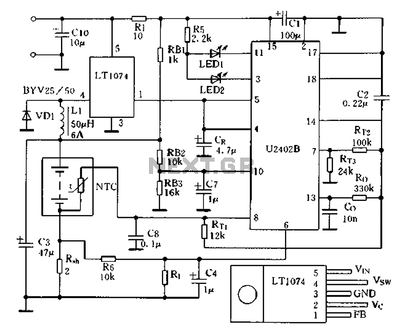
Charging circuit from the DC power supply switching power supply control The charging circuit described is designed to operate with a DC power supply, utilizing a switching power supply control mechanism. This type of circuit is commonly employed in applications...
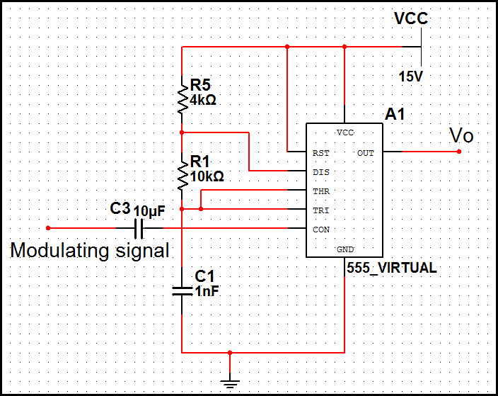
In pulse position modulation, the amplitude and width of the pulses are kept constant, while the position of each pulse with reference to the position of the reference pulse is changed according to the instantaneous sampled value of the...
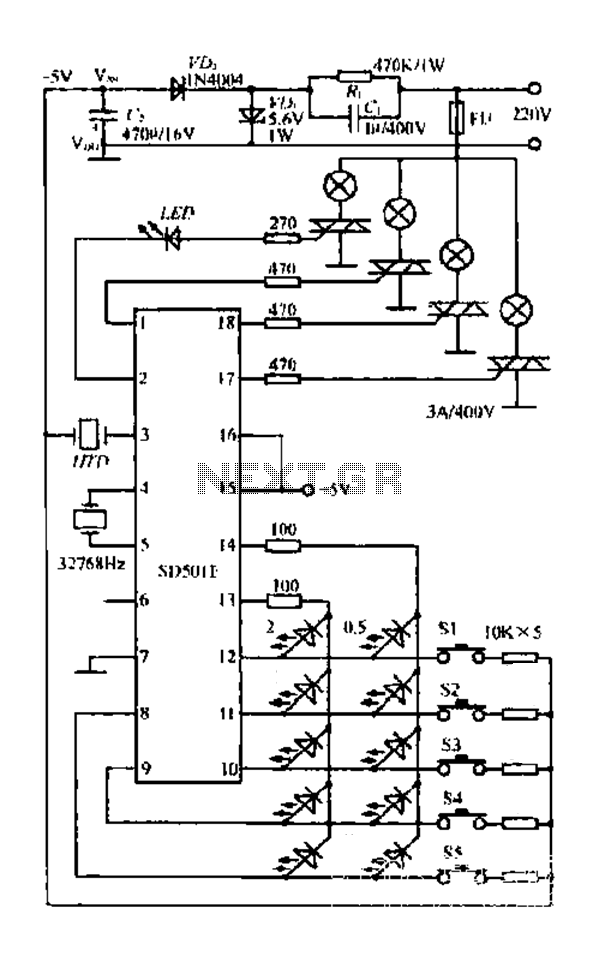
The FIG SD501E is a J tie fan integrated circuit (IC) characterized by progressive timing and three operational modes: strong, medium, and weak. It features three types of output settings and includes an electrical swing mechanism. The device is...
National Semiconductor (NS Company) produces audio integrated circuits (ICs) that offer wide frequency response and low noise. These circuits provide excellent performance across all NS products. The circuit illustrated in Figure 3-12 includes a preamplifier and a singing equalizer...